Self-circulation dust removal chamber for environmental protection engineering and application method thereof

A self-circulating, environmental protection engineering technology, applied in the direction of cleaning methods using gas flow, cleaning methods and utensils, chemical instruments and methods, etc., can solve the inability to achieve full-body cleaning, the impact of the environment and the physical and mental health of workers, and dust collectors Clean up problems such as limited angles to achieve the effect of improving dust removal efficiency, improving dust efficiency, and reducing pollution

Pending Publication Date: 2021-12-31
SHANDONG YOUBANG FERTILIZER IND & TECHCO
View PDF0 Cites 0 Cited by
  • Summary
  • Abstract
  • Description
  • Claims
  • Application Information

AI Technical Summary

Problems solved by technology

[0004] The purpose of the present invention is to provide a self-circulating dust removal room for environmental protection projects and its use method, aiming to solve the problem that in the prior art, workers use the dust collector to clean up the dust on their bodies, but the cleaning angle of the dust collector is limited, and it is impossible to achieve full-body cleaning. The cleaning of the workers, the dust that is not cleaned up on the workers will affect the environment and the physical and mental health of the workers.

Method used


Image

  • Self-circulation dust removal chamber for environmental protection engineering and application method thereof
  • Self-circulation dust removal chamber for environmental protection engineering and application method thereof
  • Self-circulation dust removal chamber for environmental protection engineering and application method thereof

Examples


Embodiment 1

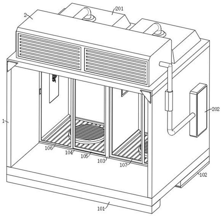
[0038] see Figure 1-Figure 8 , the present invention provides the following technical solutions:

[0039] A self-circulating dust removal chamber for environmental protection engineering, comprising:

[0040] The dust removal chamber main body 1, the bottom inner wall of the dust removal chamber main body 1 is symmetrically provided with two dust removal grooves;

[0041] The air jet dedusting assembly, the air dedusting assembly includes an air pump 2 and two dust removal seats 201, the air pump 2 is fixedly connected to the upper end of the dust removal chamber main body 1, and the two dust removal seats 201 are all arranged on the upper part of the dust removal chamber main body 1, the two dust removal seats 201 and The air pumps 2 are communicated through pipelines;

[0042] A partition 103, the partition 103 is fixedly connected to the upper and lower inner walls of the main body 1 of the dust removal chamber, and the inner walls of the two dust removal tanks are fixed...


PUM


Abstract

The invention provides a self-circulation dust removal chamber for environmental protection engineering and an application method thereof, and belongs to the technical field of dust removal chambers for environmental protection engineering. The self-circulation dust removal chamber for environmental protection engineering comprises a dust removal chamber body, an air injection dust removal assembly and partition plates, wherein two dust removal grooves are symmetrically formed in the bottom inner wall of the dust removal chamber body; the air injection dust removal assembly comprises an air pump and two dust removal bases; the air pump is fixedly connected to the upper end of the dust removal chamber body; the two dust removal bases are both arranged on the upper part of the dust removal chamber body; the two dust removal bases communicate with the air pump through pipelines; the partition plates are fixedly connected to the upper inner wall and the lower inner wall of the dust removal chamber body; and the inner walls of the two dust removal grooves are fixedly connected with dust collection grids. An operator selects different modes to clean dust on the surface of the operator according to the amount of dust on the surface of the body, and multi-angle cleaning is conducted on the dust on the surface of the body of the operator in a whole body cleaning mode, so that the dust removal efficiency is effectively improved, and the pollution of dust to the environment is reduced.

Description

technical field [0001] The invention belongs to the technical field of dust removal chambers for environmental protection engineering, and in particular relates to a self-circulating dust removal chamber for environmental protection engineering and a usage method thereof. Background technique [0002] The dust removal room is a dust removal room specially used for environmental protection projects. The dust removal room is mainly composed of a ventilation system, a manual dust collector and control equipment. After the personnel perform dust removal operations, a large amount of dust will be absorbed on the dust-proof clothing. The dust on the body surface needs to be cleaned. [0003] In the prior art, there is a dust collector in the dust removal room for environmental protection projects, and the workers use the dust collector to clean the dust on their bodies, but the cleaning angle of the dust collector is limited, and it is impossible to clean the whole body, and the u...

Claims


Application Information

Patent Timeline
IPC IPC(8): B08B5/02B08B13/00
CPCB08B5/02B08B13/00
Inventor 张辉黄剑王大伟郑广建黄腾飞窦隔胡爱国吴新光房美才杜飞
Owner SHANDONG YOUBANG FERTILIZER IND & TECHCO
Why Eureka
Try Eureka