Thin metal plate laser cutting device and discharging method thereof

A technology of laser cutting and laser cutting head, which is applied in the direction of laser welding equipment, metal processing equipment, welding equipment, etc., can solve the problems of high work intensity, long time-consuming manual collection of product recycling waste, low efficiency, etc., and achieve the goal of improving work efficiency Effect

Active Publication Date: 2021-12-31
广东铭鑫机电装配科技有限公司
View PDF12 Cites 8 Cited by
  • Summary
  • Abstract
  • Description
  • Claims
  • Application Information

AI Technical Summary

Problems solved by technology

[0004] In view of the above-mentioned related technologies, the inventor believes that the existing laser cutting machines have the defects of manual collection of products, long time-consuming recycling of waste materials, high work intensity and low efficiency

Method used


Image

  • Thin metal plate laser cutting device and discharging method thereof
  • Thin metal plate laser cutting device and discharging method thereof
  • Thin metal plate laser cutting device and discharging method thereof

Examples


Embodiment Construction

[0044] The following is attached Figure 1-5 The application is described in further detail.

[0045] The embodiment of the present application discloses a thin metal plate laser cutting device.

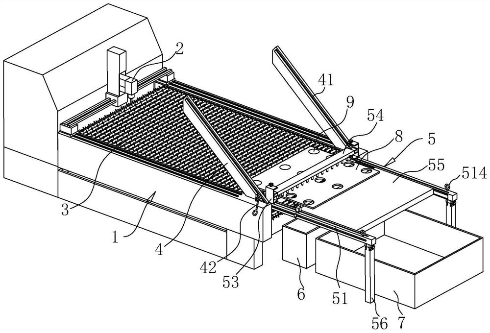
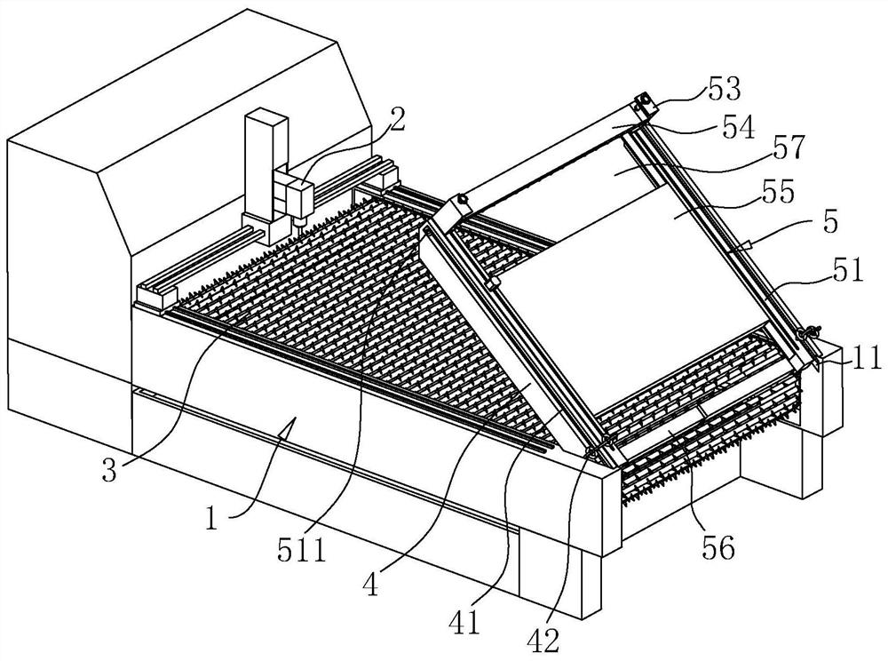
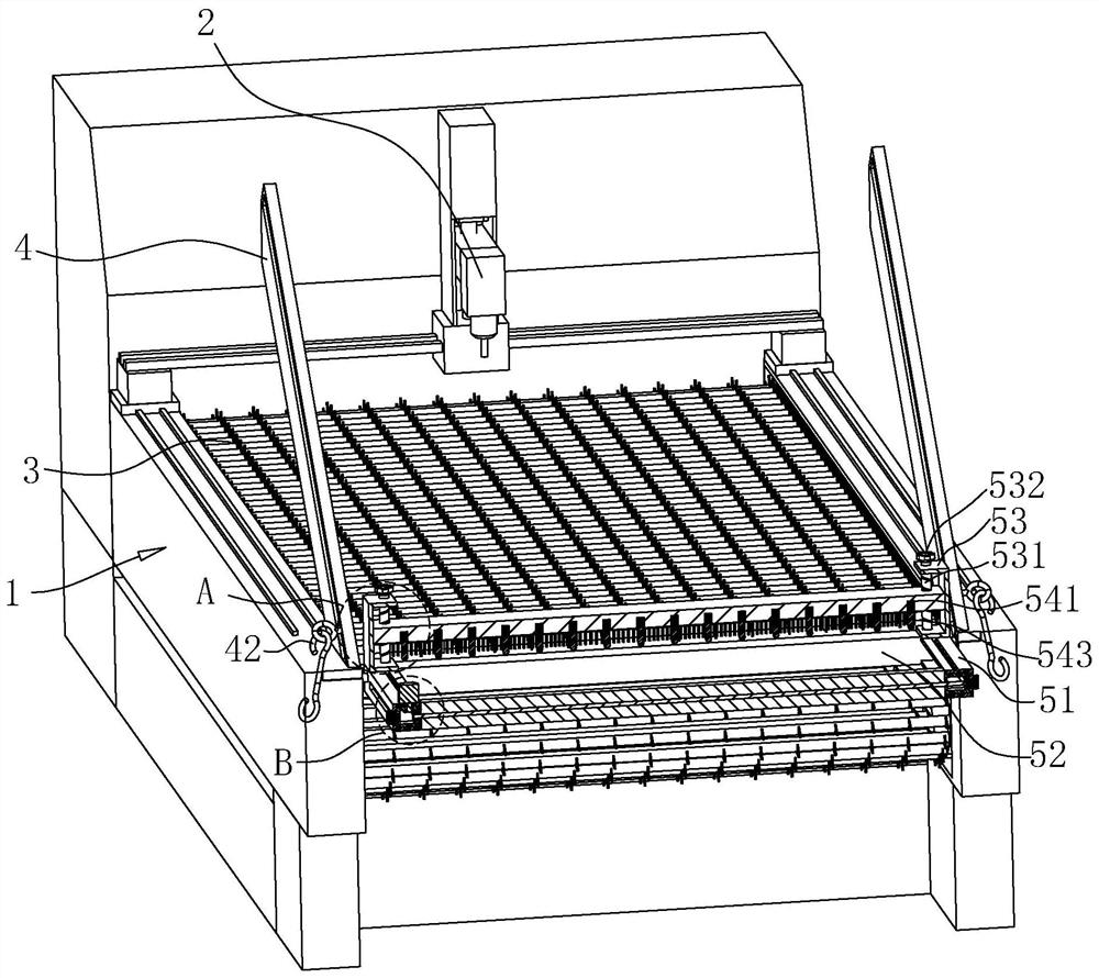
[0046] refer to figure 1 with figure 2 , the laser cutting machine includes a base 1 and a cutting head device, the cutting head device includes a laser cutting head 2 and an electric slide rail for driving the laser cutting head 2 to move along the x-axis, y-axis and z-axis directions and for driving the laser cutting head The cylinder that the head 2 moves along the z-axis direction; the base 1 is provided with a sprocket conveyor 3 for pushing the plate, the plate is placed on the sprocket conveyor 3, and the laser cutting head 2 moves to cut the plate.

[0047] refer to figure 1 with figure 2 , the laser cutting machine also includes a discharge frame 5, the discharge frame 5 is located on one side of the discharge direction of the machine base 1, the discharge frame 5 inc...


PUM


Abstract

The invention relates to a thin metal plate laser cutting device and a discharging method thereof. The cutting device comprises a machine base, a laser cutting head, a chain wheel type conveying piece used for conveying plates and a discharging frame, and the discharging frame comprises two transverse rods and a supporting plate located between the two transverse rods; one ends of the two transverse rods are slidably connected with the two sides of the machine base respectively, and the other ends of the two transverse rods are rotatably provided with supporting rods; the supporting plate can be vertically overturned, and when the supporting plate rotates to a horizontal state, the supporting plate is flush with the upper surface of the chain wheel type conveying piece; a driving assembly used for driving the supporting plate to rotate is arranged on the discharging frame; a material collecting opening is reserved between the supporting plate and the chain wheel type conveying piece; and a separating mechanism used for separating the products from a plate frame is arranged above the material collecting opening of the discharging frame. The device further comprises a material collecting box with an upward opening and a waste material box with an upward opening, wherein the material collecting box is located below the material collecting opening, and the waste material box is located below the supporting plate. The device disclosed by the invention has the effects that the product and the plate frame are automatically separated and collected, and the working efficiency is improved.

Description

technical field [0001] The present application relates to the field of cutting machines, in particular to a thin metal plate laser cutting device and a blanking method thereof. Background technique [0002] Laser cutting is to focus the laser emitted by the laser into a high power density laser beam through the optical path system. The laser beam irradiates the surface of the workpiece to make the workpiece reach the melting point or boiling point. At the same time, the high-pressure gas coaxial with the beam will blow away the molten or gasified metal. purpose of cutting. Laser cutting has the advantages of fast cutting speed, high production efficiency and small heat-affected zone. It has become one of the main cutting methods for thin metal sheets and is widely used in the field of sheet metal processing. [0003] Existing laser cutting machines usually include machine base, cutting head driving device, laser cutting head and controller. The cutting head driving device ...

Claims


Application Information

Patent Timeline
Patent Type & Authority Applications(China)
IPC IPC(8): B23K26/38B23K26/70
CPCB23K26/38B23K26/702Y02P70/10
Inventor 张杰鑫
Owner 广东铭鑫机电装配科技有限公司
Why Eureka
Try Eureka