Cloth bonding device

A bonding device and cloth technology, applied in lamination device, lamination auxiliary operation, lamination, etc., can solve problems such as low efficiency, weak cloth bonding, gaps, etc., to ensure the bonding quality and ensure the adhesion Combine processing quality and avoid loose effect

Pending Publication Date: 2021-12-31
溆浦县顺成服装有限公司
View PDF6 Cites 0 Cited by
  • Summary
  • Abstract
  • Description
  • Claims
  • Application Information

AI Technical Summary

Problems solved by technology

[0003] At present, most of the existing products on the market use manual bonding, which is extremely inefficient, and some of them use bonding equipment for bonding work, but the feeding device of the equipment is only a simple feeding wheel for feeding work, and some cloth surfaces are stained with a lot When bonding, the cloth is prone to problems such as weak bonding and gaps. Therefore, a cloth bonding device is proposed to address the above problems

Method used


Image

  • Cloth bonding device
  • Cloth bonding device
  • Cloth bonding device

Examples


Embodiment 1

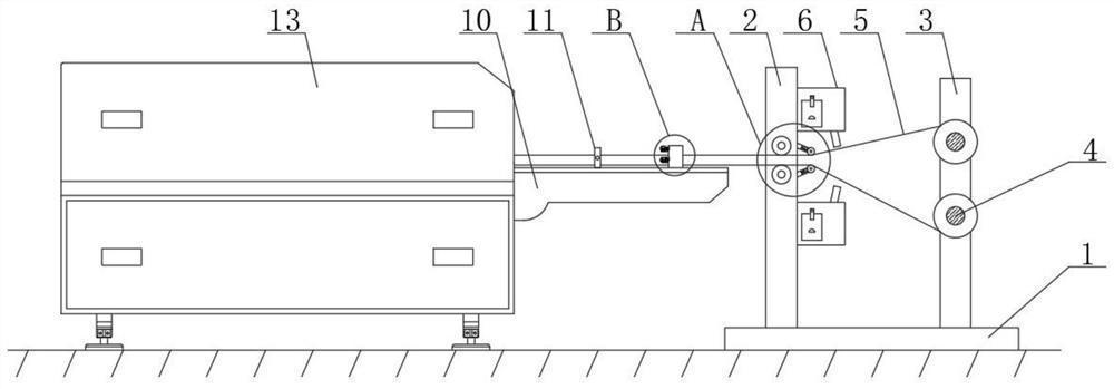
[0028] see figure 1 , figure 2 , image 3 , Figure 4 , Figure 5 , Figure 6 , Figure 7 and Figure 8 , the present invention provides a technical solution:

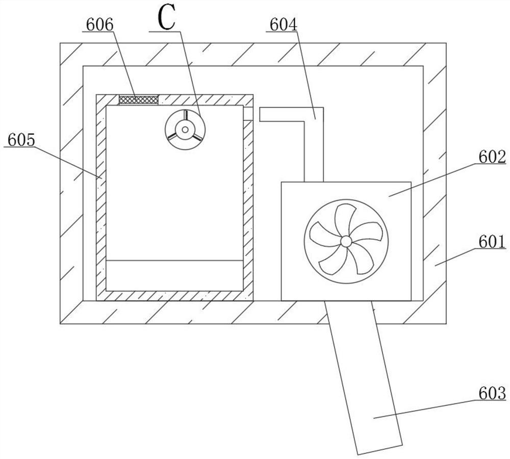
[0029]A fabric bonding device, comprising a base 1 and a left fixing frame 2, the left side fixing frame 2 distributed front and rear is fixedly connected to the left side of the upper end surface of the base 1, and the right side fixed frame distributed front and rear is fixedly connected to the right side of the upper end surface of the base 1. The side fixing frame 3 and the inner side of the right side fixing frame 3 are rotatably connected with a cloth-discharging tray 4 distributed up and down, and a cloth layer 5 is arranged on the outside of the cloth-releasing tray 4, and a dust suction device 6 is connected to the right side of the left side fixing frame 2. The dust collection device 6 includes a dust collection box 601 and a fan 602. The left side of the dust collection box 601 is fixedly connected t...

Embodiment 2

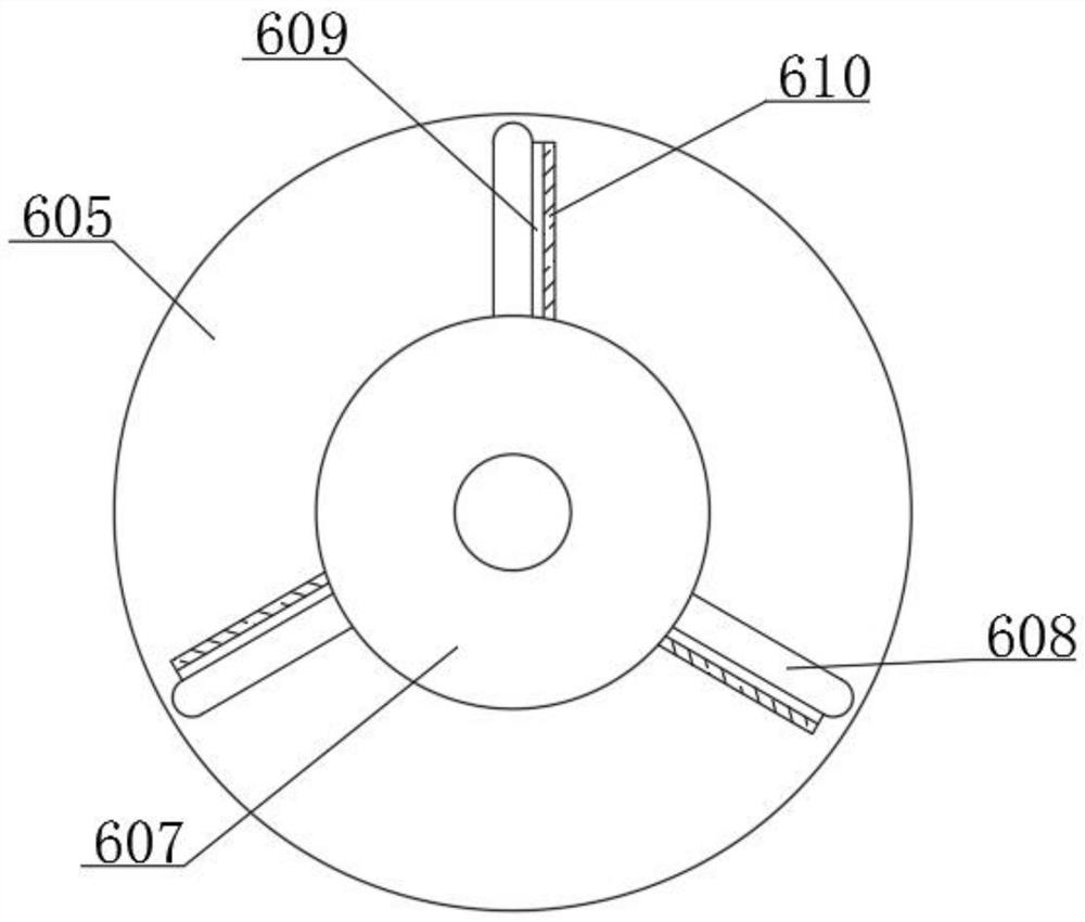
[0032] In embodiment 2, the same part as embodiment 1 is not described in detail, and the difference is that when a large amount of threads are stuck on the surface of its sub-Velcro 610, at this time, the sub-Velcro 610 can be torn off, and then the sub-Velcro can be fixed. The surface of 610 is cleaned, and then bonded together with the mother Velcro 609, which is convenient for continued use next time and avoids waste of resources.


PUM


Abstract

The invention relates to the technical field of cloth bonding, in particular to a cloth bonding device which comprises a base and a left fixing frame. The left fixing frame distributed front and back is fixedly connected to the left side of the upper end face of the base. A right fixing frame distributed front and back is fixedly connected to the right side of the upper end face of the base. The inner side of the right fixing frame is rotatably connected with cloth placing discs which are distributed up and down, and a cloth layer is arranged on the outer sides of the cloth placing discs. The right side of the left fixing frame is connected with a dust suction device. The dust suction device comprises a dust suction box and a fan. The left side of the dust suction box is fixedly connected with the left fixing frame, and the fan is fixedly connected into the dust suction box. According to the device, through the arrangement of the dust suction box, the fan, a collecting box, a filter screen, a rotary drum, a hollowed-out plate, a mother hook-and-loop fastener and a son hook-and-loop fastener, air can be driven to flow through starting of the fan, thread residue dust on the surface of the cloth layer can be sucked in, impurities can be treated, the influence on subsequent bonding is avoided, and the bonding quality is guaranteed.

Description

technical field [0001] The invention relates to the technical field of cloth bonding, in particular to a cloth bonding device. Background technique [0002] Cloth is a commonly used material in decorative materials, including chemical fiber carpets, non-woven wall coverings, linen cloth, nylon cloth, colored tape, flannel and other cloth. The main force that cannot be ignored in the sales space, a large number of fabrics are used for wall decoration, partition, and background treatment, which can also form a good commercial space display style. Fabric bonding devices are often used in fabric production. It is a sponge, Materials such as silicone are heated by flames to make them molten, and the cloth is bonded to these materials by pressing rollers. [0003] At present, most of the existing products on the market use manual bonding, which is extremely inefficient, and some of them use bonding equipment for bonding work, but the feeding device of the equipment is only a simp...

Claims


Application Information

Patent Timeline
Patent Type & Authority Applications(China)
IPC IPC(8): B32B38/16B32B38/18B32B37/00
CPCB32B38/162B32B38/1875B32B38/1825B32B37/0007
Inventor 夏燕
Owner 溆浦县顺成服装有限公司
Why Eureka
Try Eureka