
Clamp for electroplating machining production

A fixture and electric cylinder technology, which is applied in the field of fixtures for electroplating processing, can solve the problems of reducing product electroplating efficiency, wasting labor, wasting electroplating time, etc., and achieve the effects of reducing product shedding rate, saving labor waste, and improving electroplating efficiency

Inactive Publication Date: 2021-12-31
江苏五度智能金属表面处理有限公司
View PDF10 Cites 1 Cited by
  • Summary
  • Abstract
  • Description
  • Claims
  • Application Information

AI Technical Summary

Problems solved by technology

[0005] In order to make up for the deficiencies of the prior art, manual operations are required to fix the product with a jig and open the jig to remove the electroplated product. However, for a large number of electroplated products, manual operation to fix and open the jig will waste a lot of electroplating time, reduces the electroplating efficiency of products, and also wastes a lot of labor. The invention proposes a fixture for electroplating processing production

Method used


Image

  • Clamp for electroplating machining production
  • Clamp for electroplating machining production
  • Clamp for electroplating machining production

Examples


Embodiment 1

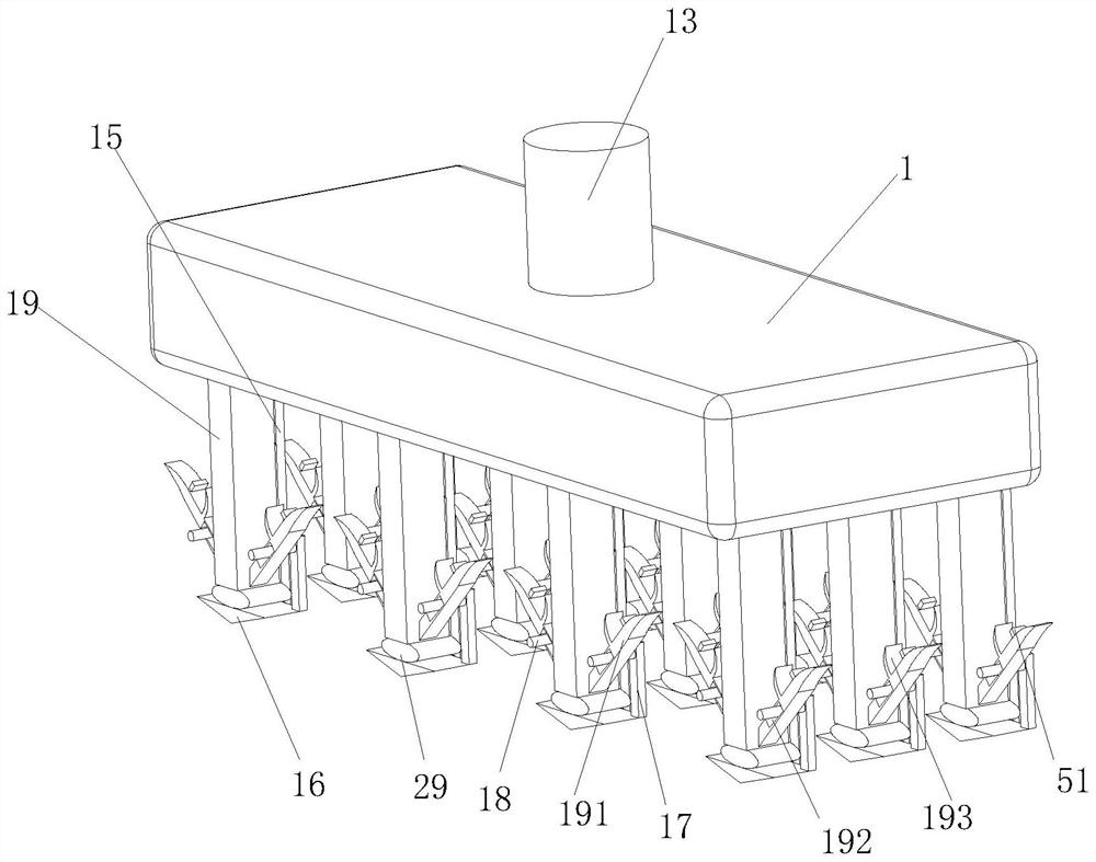
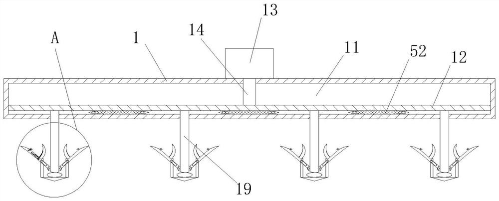
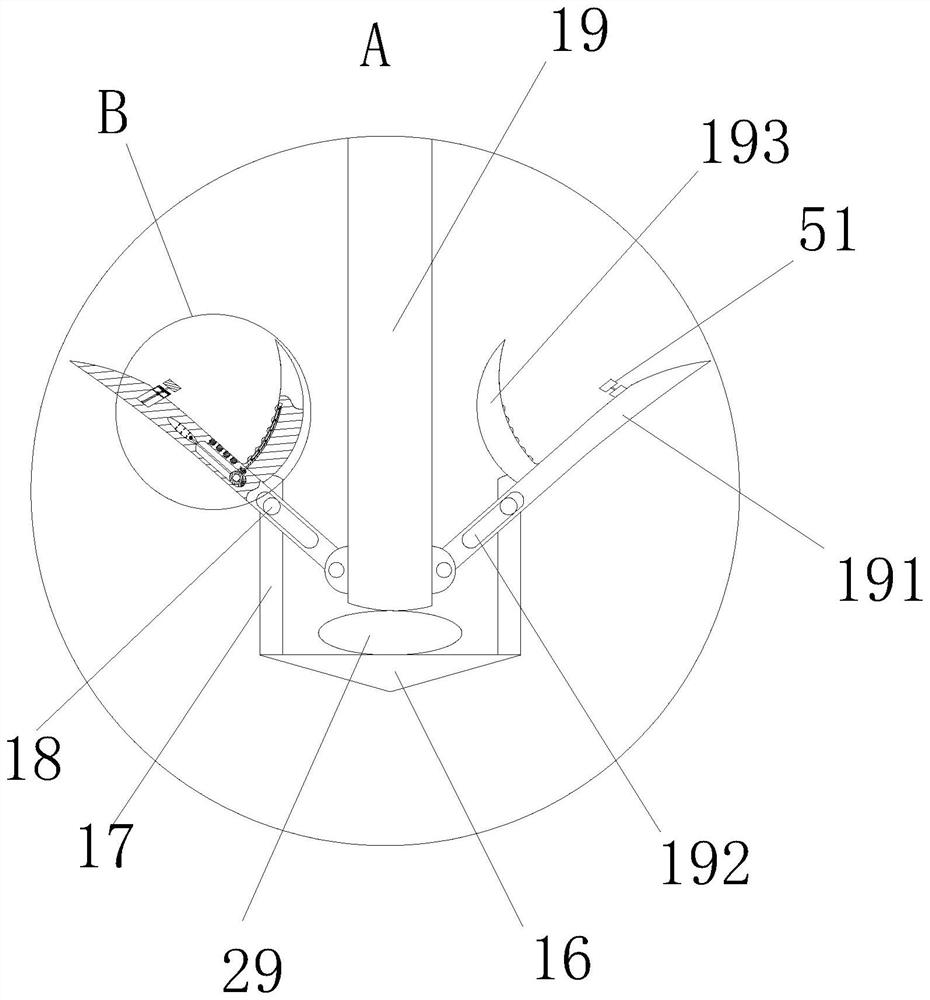
[0033] like Figure 1 to Figure 8 As shown, a jig for electroplating processing production according to the present invention includes a support plate 1; a first cavity 11 is opened in the support plate 1, and a moving plate 12 is slidably connected to the first cavity 11. ; The top of the support plate 1 is fixedly connected with an electric cylinder 13, and the electric cylinder 13 is provided with an electric rod 14, and the electric rod 14 extends into the first cavity 11 and is fixed on the top of the moving plate 12; the support plate 1. A group of fixed blocks 16 are fixedly connected to the bottom end through the fixed column 15; a pair of symmetrically distributed vertical plates 17 are fixed to the fixed blocks 16, and fixed shafts 18 are fixed to the vertical plates 17; the bottom of the moving plate 12 A moving rod 19 is fixedly connected to the position of the end relative to the fixed block 16; the moving rod 19 runs through the first cavity 11, and the two sides...

Embodiment 2

[0043] like Figure 9 As shown in Comparative Example 1, as another embodiment of the present invention, a set of anti-slip lines 47 are provided in the roller 41; during operation, the rotation of the roller 41 can not only loosen the electroplated product but also reduce friction In order to prevent sliding friction between the roller 41 and the product, the roller 41 is provided with anti-skid lines 47, which can avoid the product of sliding friction and ensure the rotation of the roller 41.

[0044]Working principle: When it is necessary to fix a product that needs to be electroplated, start the electric cylinder 13 to drive the electric rod 14 to move down, and the downward movement of the electric rod 14 will drive the moving plate 12 to move down, and the moving plate 12 will drive the moving rod 19 to move down, and the moving rod 19 moves down through the fixed shaft 18 and the first chute 192, so that the end of the hanging plate 191 is tilted, and people directly ha...


PUM


Abstract

The invention belongs to the technical field of electroplating machining, and particularly relates to a clamp for electroplating machining production. The clamp comprises a supporting plate, wherein a first cavity is formed in the supporting plate, and a moving plate is slidably connected into the first cavity; an electric cylinder is fixedly connected to the top end of the supporting plate, an electric rod is arranged in the electric cylinder, and the electric rod extends into the first cavity and is fixedly connected to the top end of the moving plate; the bottom end of the supporting plate is fixedly connected with a set of fixing blocks through fixing columns; and a pair of symmetrically-distributed vertical plates is fixedly connected to the fixing blocks, and a fixing shaft is fixedly connected to the vertical plates. The invention provides the clamp for electroplating machining production to solve the problems that manual operation is needed when a clamp is used for fixing a product and the clamp is opened to take down an electroplated product, but for a large batch of electroplated products, the manual operation for fixing and opening the clamp wastes a large amount of electroplating time, the product electroplating efficiency is reduced, and a large amount of labor is wasted.

Description

technical field [0001] The invention belongs to the technical field of electroplating processing, and specifically relates to a jig for electroplating processing production. Background technique [0002] Electroplating is the process of plating a thin layer of other metals or alloys on some metal surfaces by using the principle of electrolysis; electroplating fixtures can have different types of fixtures according to the shape of the part, the technical requirements of the coating, the electroplating process and the size of the equipment. [0003] There are also some technical solutions about electroplating processing technology in the prior art. For example, a Chinese patent with application number 2017101471424 discloses a slider electroplating quick fixture and an electroplating fixture assembly. A handle is installed on the upper splint. The handle Sliding relative to the upper splint and rotating relative to the lower splint, the handle and the lower splint are also con...

Claims


Application Information

Patent Timeline
Patent Type & Authority Applications(China)
IPC IPC(8): C25D17/06C25D21/00
CPCC25D17/06C25D21/00
Inventor 杨展平
Owner 江苏五度智能金属表面处理有限公司
Learn More