Method for improving precision of tire section scanning image

A cross-sectional scanning image and tire technology, which is applied to measuring devices, instruments, and optical devices, etc., can solve the problems of analysis result errors, failure to take into account, contour differences, etc., so as to improve the authenticity, improve accuracy, and make up for technical gaps. Effect

Pending Publication Date: 2021-12-31
KENDA RUBBER CHINA
View PDF1 Cites 0 Cited by
  • Summary
  • Abstract
  • Description
  • Claims
  • Application Information

AI Technical Summary

Problems solved by technology

[0003] The tire section is cut from the finished tire, and there will be two problems after cutting: the first is that due to the release of internal stress, the tire section profile will be quite different from the designed tire section profile; the second is due to the tire The cut surface does not necessarily pass through the tire rotation center. During the tire cutting process, when a cut surface passes through the tire rotation center, the cut surface is accurate, but generally the two cut surfaces do not pass through the tire rotation center, such as figure 1 For the cutting method shown, if the analysis process is carried out according to the section passing through the center of the tire, there will be a large error in the analysis result. The larger the tire, the larger the error will be
[0004] After searching, the invention patent with the publication number CN111795645A: a precise tire section binding method discloses a tire section fixing method, which uses a binding plate to completely bind the tire section to ensure that the tire section profile is consistent with the finished tire section profile during testing The consistency of the tire section improves the detection accuracy of the tire section, but this patent does not take into account the fact that the section size that does not pass through the center of the tire is inconsistent with the section size that passes through the center of the tire

Method used


Image

  • Method for improving precision of tire section scanning image
  • Method for improving precision of tire section scanning image
  • Method for improving precision of tire section scanning image

Examples


Embodiment

[0040] A method for improving the accuracy of tire section scanning images, comprising the steps of:

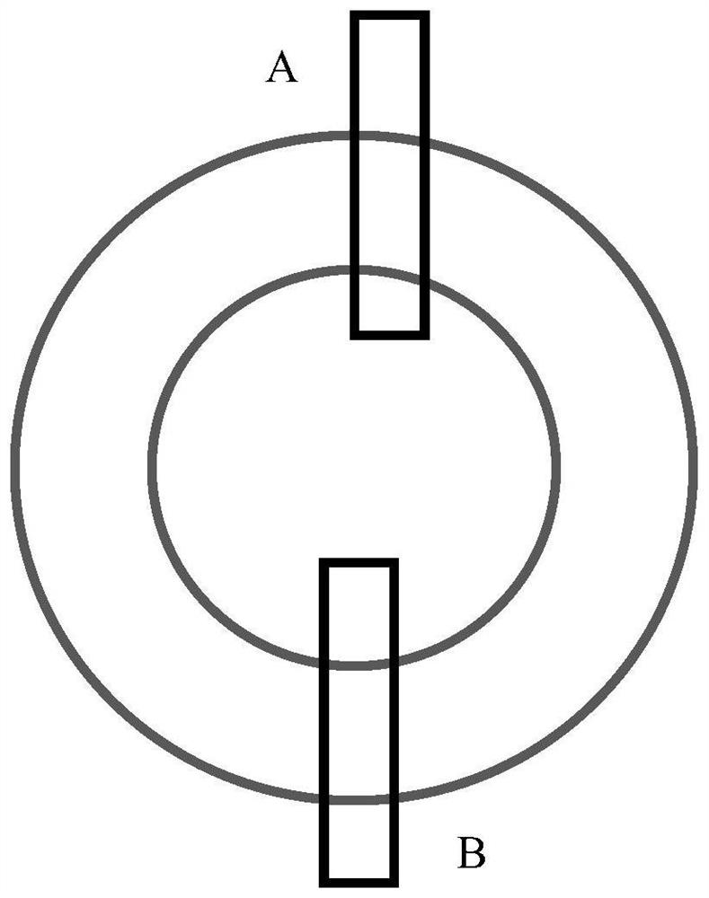
[0041] Such as figure 2 As shown, the first step: extract the tire contour line according to the tire design drawings. When the tire is a centrally symmetrical circle, extract the half-tire contour line; when the tire is non-centrosymmetrically circular, this situation is relatively rare. The outline of the whole tire needs to be extracted, and the extraction of the outline of the tire in this step can be performed by means of cad software.

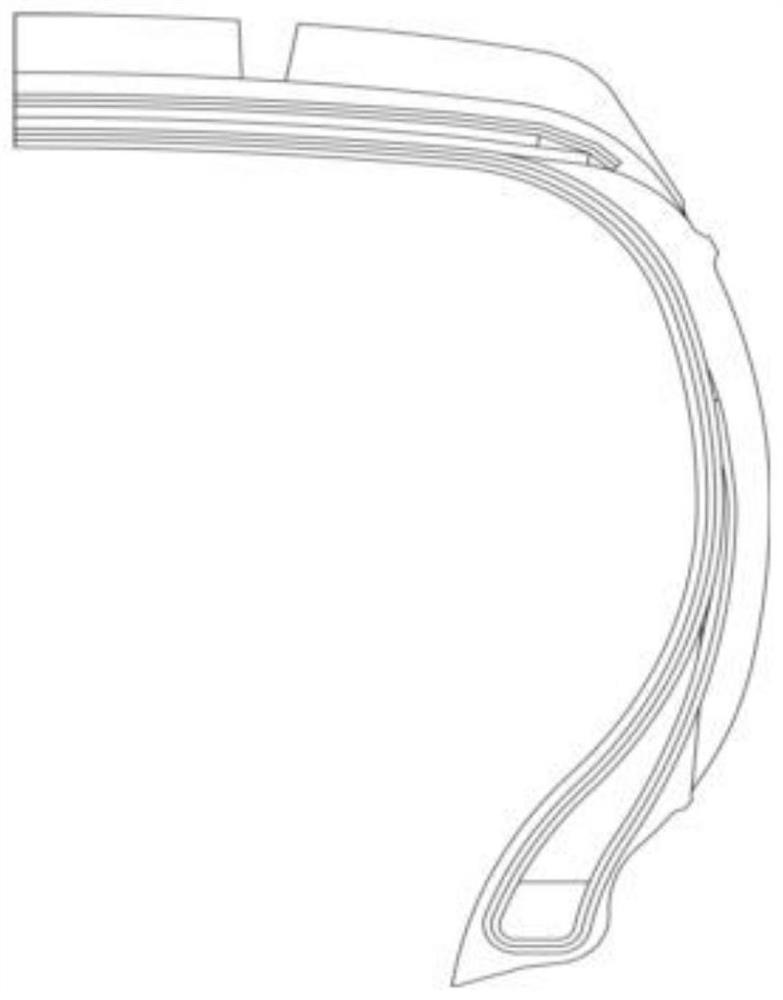
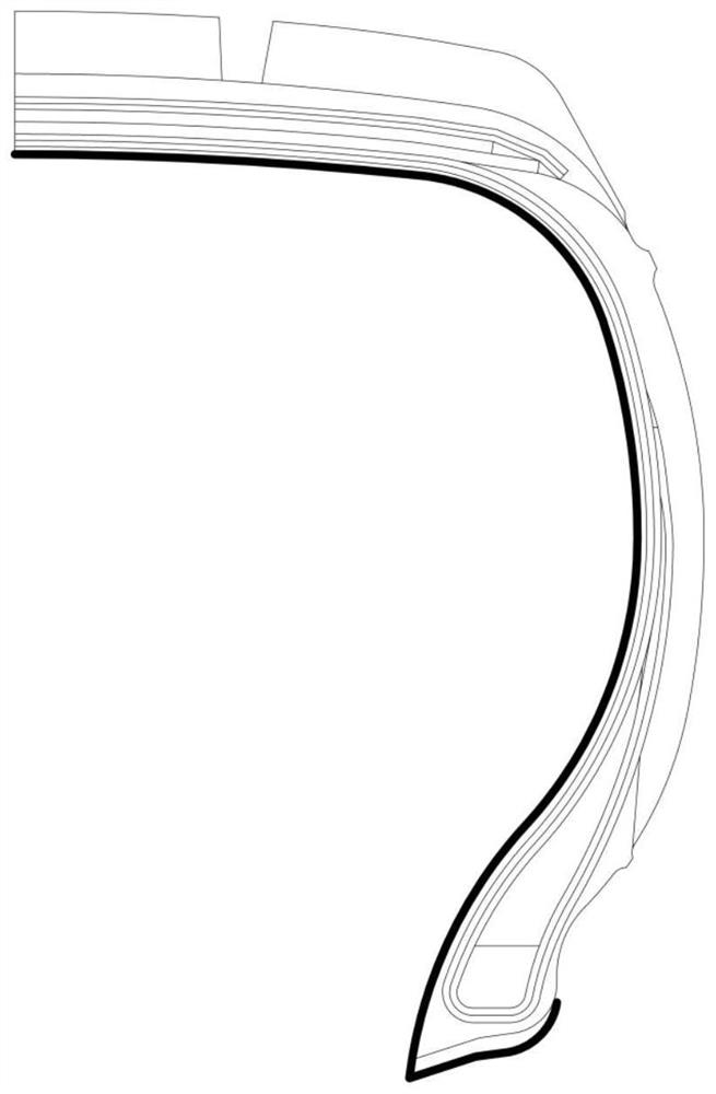
[0042] Such as image 3 and Figure 4 As shown, the second step: Import the tire outline obtained in the first step above into the 3D software. The tire itself has different structural layers, delete the outer outline, and only keep the inner outline, and then make a positioning fixture based on the inner outline ;

[0043] Such as image 3 , Figure 4 and Figure 5 As shown, the inner contour line obtained above includes the inn...


PUM


Abstract

The invention discloses a method for improving the precision of a tire section scanning image. The method comprises the following steps: extracting a tire contour line; deleting to obtain an inner contour line; obtaining a symmetrical closed clamp pattern; rotating to generate a three-dimensional figure; building a parallel surface according to the thickness of a real tire section, and segmenting a three-dimensional model with the same height as the real section, wherein one three-dimensional model passes through a tire rotation center; segmenting into a plurality of equal-thickness models, and obtaining a three-dimensional model of the clamp symmetrically along a symmetric surface; recording the distance between an upper vertex and a lower vertex of a surface symmetric line of the three-dimensional model passing through and not passing through the rotation center, and calculating Sn; according to the type of the section of the tire, selecting a solid model for fixing and scanning, and scaling a scanned image in the direction perpendicular to the rotation axis of the tire according to the Sn proportion. By means of the mode, the cut surface scanning image which does not pass through the tire rotation center is restored to the standard cut surface scanning image which passes through the tire rotation center, and the trueness of the tire section scanning image is effectively improved.

Description

technical field [0001] The invention relates to the field of tire structure analysis, in particular to a method for improving the accuracy of tire section scanning images. Background technique [0002] The analysis of tire section is an important means in tire analysis. By measuring and analyzing the tire section, you can understand the structure of the tire and the size of each part, analyze the failed tire, find the cause of failure, improve product quality and analyze the product situation of competitors. . [0003] The tire section is cut from the finished tire, and there will be two problems after cutting: the first is that due to the release of internal stress, the tire section profile will be quite different from the designed tire section profile; the second is due to the tire The cut surface does not necessarily pass through the tire rotation center. During the tire cutting process, when a cut surface passes through the tire rotation center, the cut surface is accur...

Claims


Application Information

Patent Timeline
Patent Type & Authority Applications(China)
IPC IPC(8): G01B11/24
CPCG01B11/24
Inventor 柏林王怀亭李亚丽吴道海韩明杨银明
Owner KENDA RUBBER CHINA
Why Eureka
Try Eureka