
Dielectric filter unit and dielectric filter

A dielectric filter and dielectric resonant cavity technology, which is applied to waveguide devices, electrical components, circuits, etc., can solve the problems of large volume of dielectric filters, inability to take into account the volume, multi-resonant mode suppression performance, etc., and achieve high debuggability. and producibility effects

Active Publication Date: 2021-12-31
ZTE CORP
View PDF5 Cites 1 Cited by
  • Summary
  • Abstract
  • Description
  • Claims
  • Application Information

AI Technical Summary

Problems solved by technology

[0003] Dielectric filters are usually composed of multiple resonant cavities. The more resonant cavities, the higher the order of the filter, and the better the suppression performance, but it often leads to the larger size of the dielectric filter. At present, the general dielectric filter cannot Taking into account the requirements of volume, multi-resonance mode and suppression performance

Method used


Image

  • Dielectric filter unit and dielectric filter
  • Dielectric filter unit and dielectric filter
  • Dielectric filter unit and dielectric filter

Examples


Embodiment Construction

[0026] This part will describe the specific embodiment of the present invention in detail, and the preferred embodiment of the present invention is shown in the accompanying drawings. Each technical feature and overall technical solution of the invention, but it should not be understood as a limitation on the protection scope of the present invention.

[0027] In the description of the present invention, several means one or more, and multiple means two or more. Greater than, less than, exceeding, etc. are understood as not including the original number, and above, below, within, etc. are understood as including the original number. If the description of the first and second is only for the purpose of distinguishing the technical features, it cannot be understood as indicating or implying the relative importance or implicitly indicating the number of the indicated technical features or implicitly indicating the order of the indicated technical features relation.

[0028] In t...


PUM


Abstract

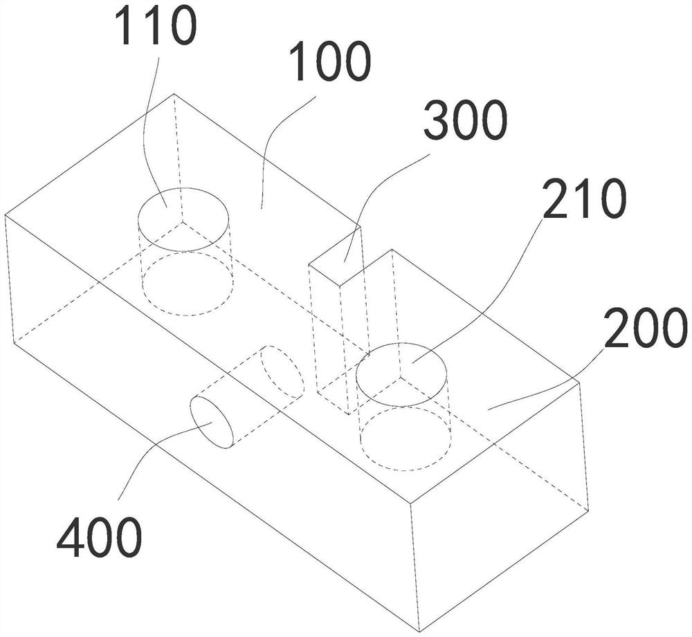
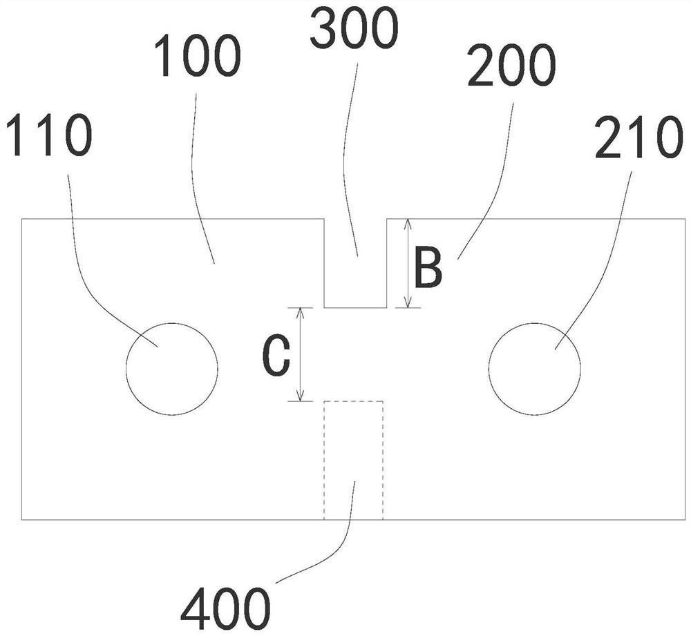
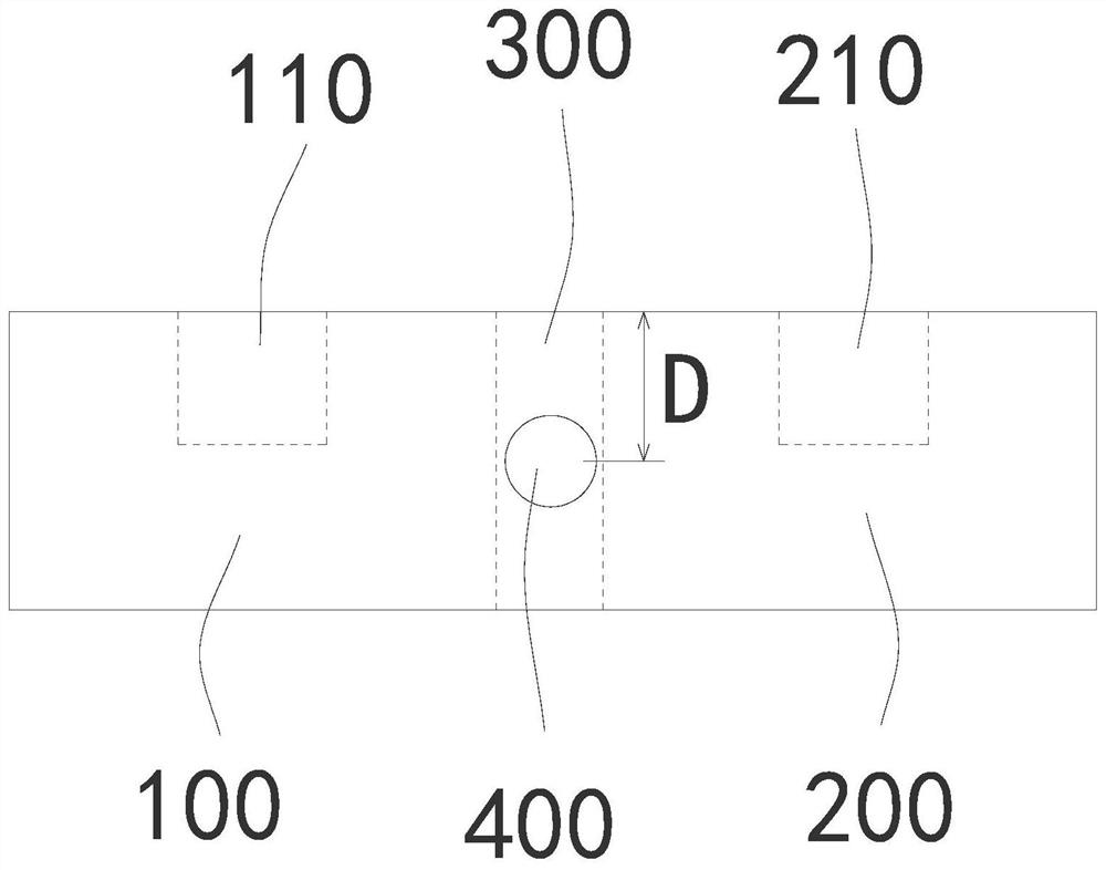
The invention discloses a dielectric filter unit and a dielectric filter. the dielectric filter unit comprises a first dielectric resonant cavity and a second dielectric resonant cavity, and the upper end face or the lower end face of the first dielectric resonant cavity is provided with a first frequency hole; the second dielectric resonant cavity is connected with the first dielectric resonant cavity, a second frequency hole is formed in the upper end face or the lower end face of the second dielectric resonant cavity, a coupling groove is formed in the joint of the first dielectric resonant cavity and the second dielectric resonant cavity, and a third frequency hole is further formed in the joint of the first dielectric resonant cavity and the second dielectric resonant cavity. And the third frequency hole is matched with the coupling groove, so that a third resonant mode is excited in the double-cavity structure, and the dielectric filter completes realization of three transmission modes under the condition that only the physical forms and the volume sizes of the two cavities are used, thereby achieving the performance of a third-order filter, generating an out-of-band transmission zero point at the same time, and having relatively high debuggeability and producibility.

Description

technical field [0001] The invention relates to the field of communication equipment, in particular to a dielectric filter unit and a dielectric filter. Background technique [0002] When the electromagnetic wave propagates in a material with high dielectric constant, its wavelength can be shortened. Using this theory, dielectric materials can be used instead of traditional metal materials. Under the same index, the volume of the filter can be reduced. Research on dielectric filters has always been a hot spot in the communication industry. Filters are important components of wireless communication products, and dielectric filters are of great significance to the miniaturization of communication products. [0003] Dielectric filters are usually composed of multiple resonant cavities. The more resonant cavities, the higher the order of the filter, and the better the suppression performance, but it often leads to the larger size of the dielectric filter. At present, the genera...

Claims


Application Information

Patent Timeline
Patent Type & Authority Applications(China)
IPC IPC(8): H01P1/208
CPCH01P1/208H01P1/2086H01P1/2084
Inventor 乔龙卜伟龚红伟武增强
Owner ZTE CORP
Learn More