Construction machine

A technology for construction machinery and operating machines, which is applied to mechanically driven excavators/dredgers, earth movers/shovels, instruments, etc., which can solve the problem of reduced operating efficiency, GNSS positioning is no longer implemented, and location and location cannot be provided. location information etc.

Pending Publication Date: 2021-12-31
NIHON KENKI CO LTD
View PDF1 Cites 0 Cited by
  • Summary
  • Abstract
  • Description
  • Claims
  • Application Information

AI Technical Summary

Problems solved by technology

[0004] In hydraulic excavators that use two GNSS antennas for GNSS positioning, GNSS positioning is no longer performed properly in cases where the GNSS antenna cannot capture the required number of satellite signals
In such a state, since the position and orientation information cannot be provided, the operation of the machine guidance and machine control has to be stopped, and the work efficiency may be reduced.

Method used


Image

  • Construction machine
  • Construction machine
  • Construction machine

Examples


no. 1 Embodiment approach

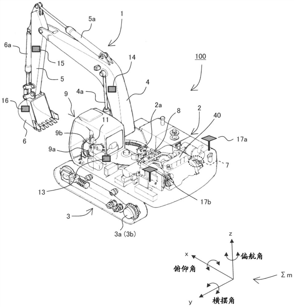
[0046] figure 1 It is a figure which shows the external appearance and a part of internal structure of the hydraulic excavator which is an example of the construction machine of this invention.

[0047] exist figure 1 Among them, the hydraulic excavator 100 includes: a multi-joint type front working machine 1 configured by connecting a boom 4, an arm 5, and a bucket (work piece) 6 as a plurality of driven parts that rotate in the vertical direction; Together with the upper revolving structure 2 and the undercarriage 3 constituting the vehicle body, the upper revolving structure 2 is mounted so as to be rotatable with respect to the undercarriage 3 . In addition, the base end of the boom 4 of the front working machine 1 is vertically supported on the front part of the upper swing body 2, and one end of the arm 5 is vertically supported on the front end of the boom 4. The other end of the rod 5 is supported by a bucket 6 so as to be rotatable in the vertical direction. The ...

no. 2 Embodiment approach

[0202] The first embodiment is a configuration using only sensors additionally attached to the hydraulic excavator 100 .

[0203] The second embodiment of the present invention achieves simplification or stabilization of calculation contents by utilizing sensors originally mounted on the hydraulic excavator 100 .

[0204] First, the features of this embodiment will be briefly described as follows.

[0205] In this embodiment, when the controller 20 judges the quality of the azimuth angle of the upper revolving body 2 calculated by the GNSS receiver 17c, it acts as the front working machine acquired by the boom IMU 14 (front attitude angle acquisition device). In order to reserve the posture angle of 1, the operation signal of the operating lever device 9a (first operating lever device) that instructs the lifting operation of the boom 4 (the operation of the front working machine 1) is input, and based on the operating signal of the operating lever device 9a, When the operatio...

no. 3 Embodiment approach

[0218] The first and second embodiments are embodiments in which a tilt angle detector represented by an IMU is used for the front working machine 1 , but the present invention can be implemented without using the tilt angle detector for the front working machine 1 .

[0219] First, the features of this embodiment will be briefly described as follows.

[0220] In the present embodiment, the hydraulic excavator 100 includes an image recognition device 35 (see Figure 8 ), the image recognition device 35 is based on at least one camera 30 or 32 or 33 (refer to Figure 8 ) to identify at least one of the attitude angle of the upper rotating body 2 and the attitude angle of the front working machine 1, and the controller 20 based on the attitude angle of the upper rotating body 2 recognized by the image recognition device 35 and the front working machine At least one of the attitude angles of 1 judges the quality of the azimuth angle of the revolving superstructure 2 calculated by ...


PUM


Abstract

In order to be able to use a GNSS and calculate accurate azimuth angles regardless of changes in the posture of a construction machine, such as the raising or lowering of a front work machine, a controller 20 has a position / posture calculation unit 20a that: determines that the quality of an azimuth angle for an upper rotation body 2, calculated by a GNSS receiver 17c, is low when at least either the posture angle of the upper rotation body 2 obtained by a body IMU 13 or the posture angle of a front work machine 1 obtained by a boom IMU 14 is at least a threshold value; executes a bias removal calculation on the basis of the azimuth angle quality and on the basis of the azimuth angle of the upper rotation body 2 calculated by the GNSS receiver 17c; calculates a corrected azimuth angle for the upper rotation body 2, on the basis of the azimuth angle for the upper rotation body 2 calculated by the GNSS receiver 17c and on the basis of the gyro bias-removed angular velocity of the upper rotation body 2; and uses this corrected azimuth angle to calculate the three-dimensional position and posture of the front work machine 1.

Description

technical field [0001] The present invention relates to construction machines such as hydraulic excavators in which an upper revolving body can rotate relative to a lower traveling body. Background technique [0002] With the countermeasures for information-based construction, we have developed a machine guidance that displays the position and posture of the multi-joint front working machine to the operator, and a machine that moves the position and posture of the front working machine along the target construction surface. The way to control the functions of the mechanical control of the hydraulic excavator. [0003] In such a hydraulic excavator, in order to cope with three-dimensional information-based construction (3D information-based construction), it is necessary to provide the position (coordinates) and orientation (orientation of the front working machine) of the hydraulic excavator itself on the construction site. In order to provide such information, conventional...

Claims


Application Information

Patent Timeline
Patent Type & Authority Applications(China)
IPC IPC(8): G06F30/17G06F30/20E02F3/30E02F3/36G06F119/02
CPCG06F30/17G06F30/20E02F3/30E02F3/36G06F2119/02G01S19/54G01S19/43E02F9/123E02F9/264E02F3/435G01S19/49G01S19/485E02F9/20E02F9/121G01S19/47
Inventor 石原新士泉枝穗小竹伸一
Owner NIHON KENKI CO LTD
Why Eureka
Try Eureka