Material transfer device for earthwork roadbed construction

A transfer device and roadbed technology, which is applied in transportation and packaging, processing of building materials, trolleys, etc., can solve the problems of inability to completely pour out transfer materials and cannot be applied to the fast-paced transfer environment, so as to avoid construction accidental injuries and perfect functions , the effect of reducing labor intensity

Pending Publication Date: 2022-01-04
CHINA CONSTR FOURTH ENG DIV +1
View PDF1 Cites 0 Cited by
  • Summary
  • Abstract
  • Description
  • Claims
  • Application Information

AI Technical Summary

Problems solved by technology

But the above-mentioned disclosed scheme has the following deficiencies: it is impossible to completely pour out the transshipment material only by the inclination of the placement box, and it is not enough to be easy to take out. , but to constantly transfer the accumulated materials to the construction site, so the materials must be completely poured out, which makes the open structure unsuitable for the fast-paced transfer environment

Method used


Image

  • Material transfer device for earthwork roadbed construction
  • Material transfer device for earthwork roadbed construction
  • Material transfer device for earthwork roadbed construction

Examples


Embodiment 1

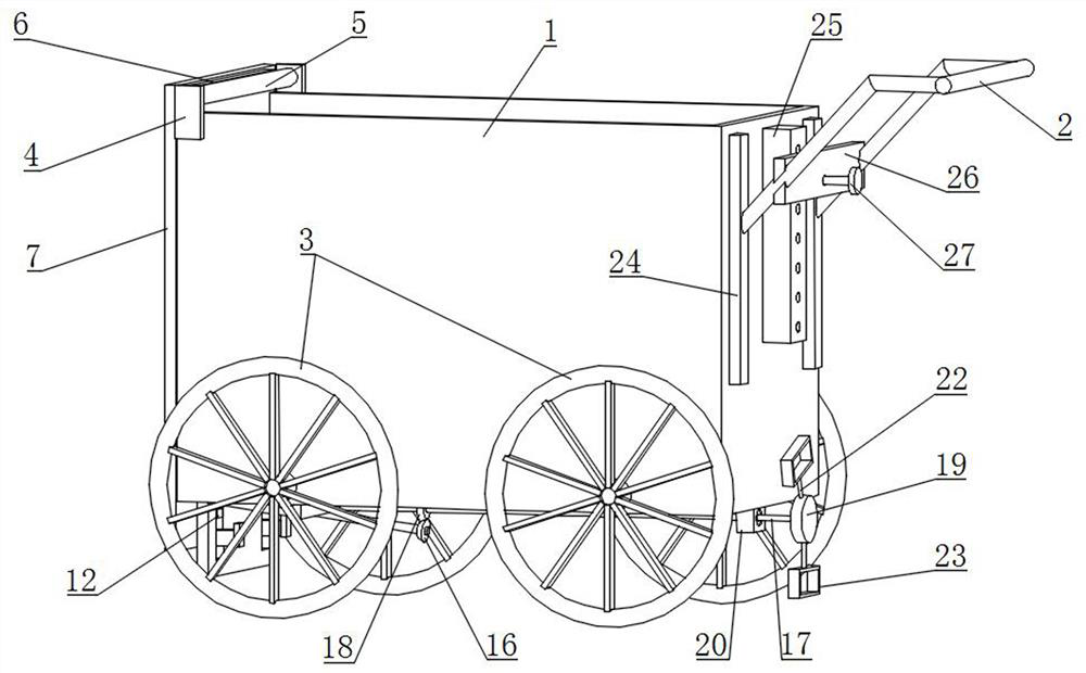
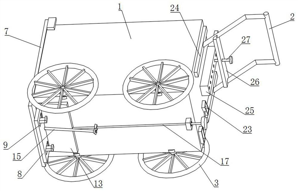
[0026] The main structure of this embodiment, such as Figure 1~4 As shown, the transfer box 1, the slide plate 8, the insertion rod 10, the first limiting plate 11, the second limiting plate 12, the triangular guide plate 13, the fixing block 14 and the screw rod 15;

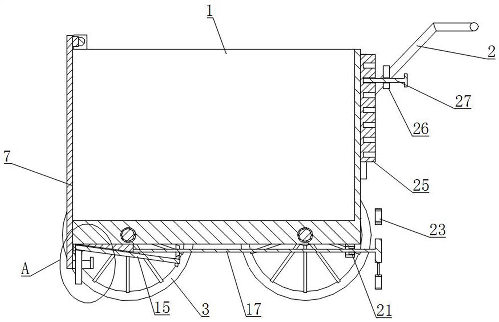
[0027] The top and the front side of the transfer box 1 are all open, the left and right sides of the bottom of the transfer box 1 are rotated to set two sets of rollers 3, the rear side of the transfer box 1 is provided with a push handle 2, and the top of the front end of the transfer box 1 is rotated to close the front opening. Sealing plate 7, the rotation direction of the sealing plate 7 is clockwise or counterclockwise, the bottom of the sealing plate 7 is located below the transfer box 1; the triangular guide plate 13 is arranged at the bottom of the transfer box 1, and the shape of the transverse section of the triangular guide plate 13 is a right angle Triangular, the hypotenuse of the right triangle i...

Embodiment 2

[0030] In this embodiment, on the basis of the foregoing embodiments, a slide rail 24, a second support plate 25, a third support plate 26 and bolts 27 are further added, as Figure 1~3 As shown, the slide rail 24 is vertically arranged on the outer wall of the rear side of the transfer box 1, and two groups of slide rails 24 are arranged, and the push handle 2 is slid and arranged on the slide rail 24 along the vertical direction; the second support plate 25 is vertically arranged on the outer wall of the rear side of the transfer box 1, and the second support plate 25 is located between two groups of slide rails 24; the third support plate 26 is arranged on the push handle 2, and the third support plate 26 and the transfer box 1 The rear side outer wall is parallel, threaded holes b are set on the third support plate 26, and multiple groups of threaded holes b are arranged side by side on the second support plate 25; the bolts 27 are matched with the threaded holes b, and the...

Embodiment 3

[0032] On the basis of the above embodiments, this embodiment further defines the structure of the rotating assembly, as shown in 1-3s, the rotating assembly includes a first bevel gear 16, a second support rod 17, a second bevel gear 18, a circular Plate 19 and the third support rod 22; the first bevel gear 16 is arranged on the screw rod 15, and the first bevel gear 16 is located at the rear side of the triangular guide plate 13; the second support rod 17 is horizontal and rotated and arranged on the triangular guide plate 13, the second support rod 17 is located between the first bevel gear 16 and the bottom of the transfer case 1, and the right end of the second support rod 17 is located at the rear side of the transfer case 1; the second bevel gear 18 is arranged on the second support rod 17 , the second bevel gear 18 meshes with the first bevel gear 16; the disc 19 is arranged on the right end of the second support rod 17; the third support rod 22 is arranged on the outer...


PUM


Abstract

The invention discloses a material transfer device for earthwork roadbed construction. The material transfer device comprises a transfer box, a sliding plate, an inserting rod, a first limiting plate, a second limiting plate, a triangular guide plate, a fixed block and a screw rod. A sealing plate and a push handle are respectively arranged on the front side and the rear side of the transfer box; the triangular guide plate is arranged at the bottom of the transfer box, the section of the triangular guide plate is a right triangle, and the hypotenuse of the right triangle faces downwards and forwards; the sliding plate is slidably arranged at the bottom of the triangular guide plate and provided with a strip-shaped groove; the inserting rod is arranged on the sealing plate and penetrates through the strip-shaped groove; the first limiting plate is arranged at the end of the insertion rod; the second limiting plate is arranged on the top groove wall of the strip-shaped groove; the fixed block is arranged at the bottom of the transfer box; and the screw rod is rotationally arranged on the fixed block. The material transferring device is reasonable in structural arrangement, complete in function, capable of improving the material transferring efficiency and guaranteeing the material transferring safety of workers and suitable for wide application and popularization.

Description

technical field [0001] The invention relates to the technical field of road construction equipment, in particular to a material transfer device for earthwork roadbed construction. Background technique [0002] The construction materials of the earthwork subgrade are mostly soil blocks, stones and concrete, etc. During the construction process, the piled materials need to be transported to the construction site. The existing practical transport devices on the construction site are mostly two-wheeled trolleys, although the structure is simple. , but it is more troublesome when unloading. It is necessary for the user to hold the push handle and turn it up over 90 degrees. The material can never slide out from the cart. The unloading labor intensity is extremely high, and sometimes some users can be seen unloading Directly lift the trolley to make it turn over and pour out the materials. The push handle of the trolley is easy to hit people, and the turned trolley is easy to tilt...

Claims


Application Information

Patent Timeline
IPC IPC(8): B62B3/04B62B5/00E04G21/16
CPCB62B3/04B62B5/00E04G21/162Y02A30/60
Inventor 苟建勇祝欢周懋辉杨涛刘强
Owner CHINA CONSTR FOURTH ENG DIV
Why Eureka
Try Eureka