
#-shaped wheel set mechanism

A wheel set and tic-tac-toe technology, which is applied in the field of metal surface treatment, can solve the problems of tic-tac-toe wheel set blockage, affect processing efficiency, interfere with processing, etc., and achieve the effect of reducing time-consuming and labor-intensive and increasing production efficiency.

Active Publication Date: 2022-01-04
ZHEJIANG MOPPER ENVIRONMENTAL TECH CO LTD
View PDF6 Cites 3 Cited by
  • Summary
  • Abstract
  • Description
  • Claims
  • Application Information

AI Technical Summary

Problems solved by technology

[0004] But because the size of the pore diameter can only allow the steel wire to pass through, if the knotting phenomenon occurs before the steel wire enters the well wheel group, it will cause the blockage of the well wheel group and interfere with subsequent processing; In the rust process, the long rust removal process line leads to the phenomenon of steel wire bending, which affects the processing efficiency
When the steel wire is knotted and bent, the staff needs to manually take out the steel wire to straighten it and then feed it to remove the rust. To take out the steel wire, the well-shaped wheel set must be disassembled first. When the original well-shaped wheel set is disassembled to take the wire, it needs The drum and the mounting plate are separated and removed, which is time-consuming and labor-intensive, which affects the efficiency of rust removal. Therefore, inventing a well-shaped wheel set mechanism is an urgent problem to be solved in the rust removal process.

Method used


Image

  • #-shaped wheel set mechanism
  • #-shaped wheel set mechanism
  • #-shaped wheel set mechanism

Examples


Embodiment

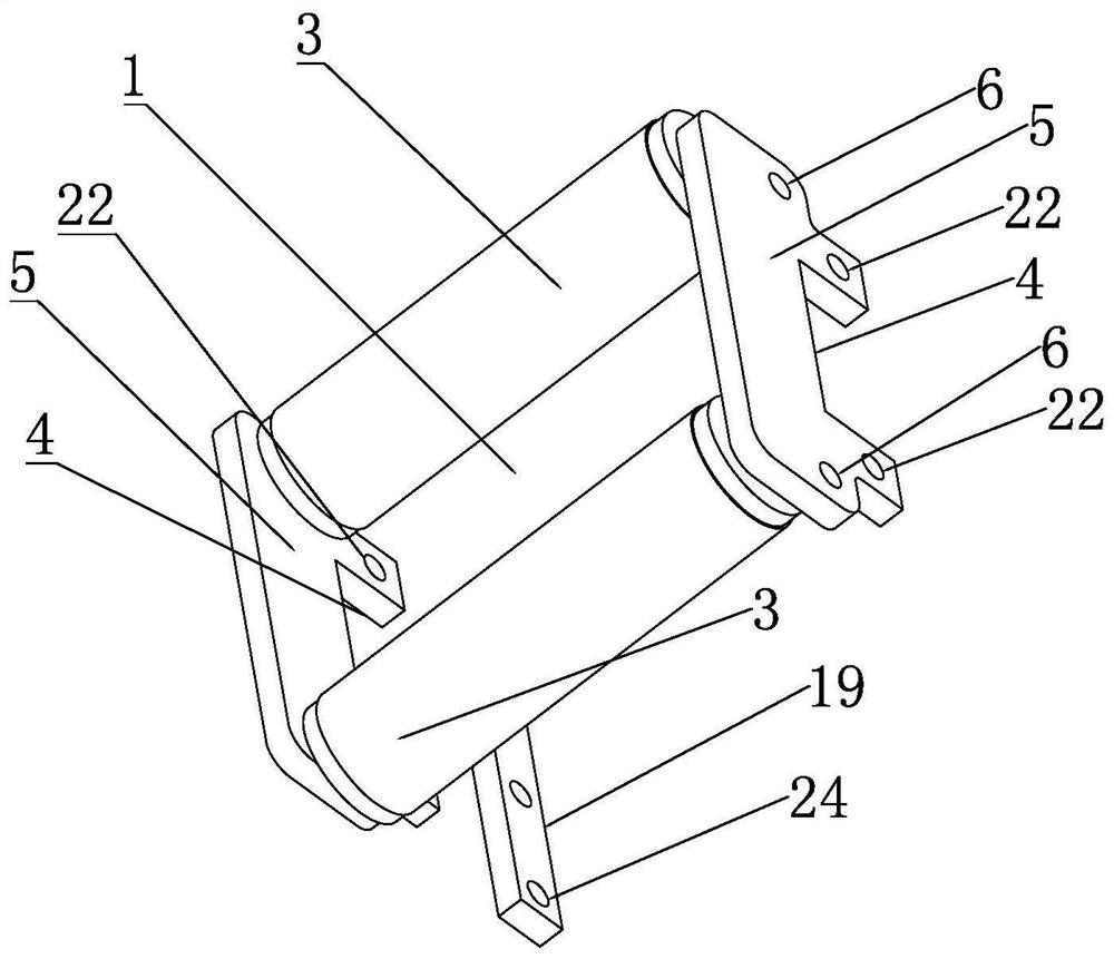
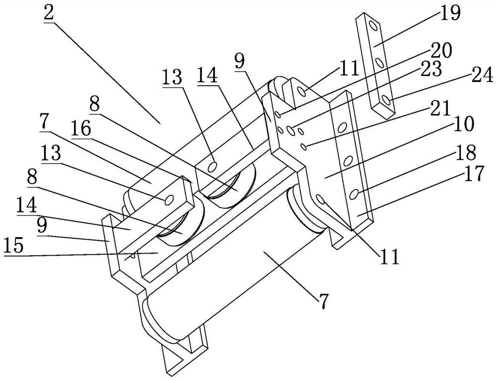
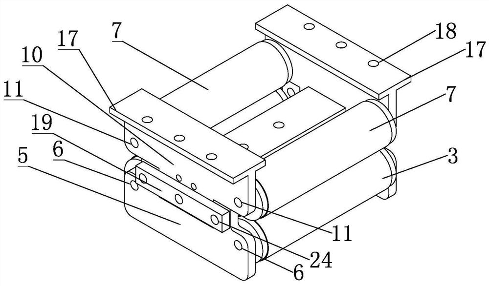
[0028] Example: as Figure 1-10 As shown, a well-shaped wheel set mechanism of the present invention includes such as figure 1 The first round shown in Group 1 and as figure 2 Second wheel set 2 shown.

[0029] like figure 1 As shown, the first wheel set 1 includes a pair of first rollers 3 and two oppositely arranged first mounting plates 5; the first rollers 3 are arranged at intervals and are respectively rotatably connected with the first mounting plates 5, so Each of the first mounting plates 5 is provided with a groove 4, two first mounting holes 6 and two first assembly threaded holes 22, and the groove 4 is concave inward in the middle of one side of the first mounting plate 5. The groove 4 is a square shape, the first roller mounting holes 6 are provided on both sides of the bottom of the groove 4 , and the first assembly threaded holes are provided on both sides of the upper part of the groove 4 . The two first rollers 3 are mounted between the two first mountin...


PUM


Abstract

The invention discloses a #-shaped wheel set mechanism. The #-shaped wheel set mechanism comprises a first wheel set and a second wheel set which are independently assembled, and the first wheel set comprises a pair of first rollers and two first mounting plates which are oppositely arranged and are each provided with a groove; the second wheel set comprises a pair of second rollers, third rollers and two second mounting plates which are oppositely arranged and are provided with a clamping block, the second rollers are spaced apart and are each rotationally connected with the second mounting plate, the third rollers are arranged between the two second rollers, and axes of the second rollers and axes of the third rollers are perpendicular to each other; a third roller shaft seat is arranged between the two second mounting plates. When the whole #-shaped wheel set is combined, the grooves and the clamping blocks are tabled, the first mounting plates and the second mounting plates are located on a same plane, and then a pair of fixing pieces stretch across the joints of the clamping blocks and the grooves and are fixedly connected with the first mounting plates and the second mounting plates. During wire taking, the two wheel sets can be separated only by detaching the pair of fixing pieces without separating and detaching the rollers and the mounting plates.

Description

technical field [0001] The invention belongs to the technical field of metal surface treatment, in particular to a well-shaped wheel set mechanism. Background technique [0002] It usually takes a period of time from the production of the steel wire to the actual use. During this period, the surface of the steel wire will rust due to various reasons, which will affect the actual use. Therefore, the surface of the steel wire needs to be derusted before using the rusted steel wire. deal with. [0003] Since the steel wire is generally coiled and placed in a roll, in the process of removing rust on the surface of the steel wire, it is necessary to change the steel wire from a coiled state to a straight state in order to enter the rust removal device for surface treatment. In the prior art, a well-shaped wheel set that can provide initial traction force to the steel wire so that it can be effectively pulled, limit the position of the steel wire and can effectively prevent the s...

Claims


Application Information

Patent Timeline
Patent Type & Authority Applications(China)
IPC IPC(8): B65H51/08B65H51/32
CPCB65H51/08B65H51/32B65H2701/39
Inventor 傅如学沈旭青
Owner ZHEJIANG MOPPER ENVIRONMENTAL TECH CO LTD
Learn More