Self-adaptive variable-speed outer cone disc type self-spinning-free traction type continuously variable transmission
A continuously variable transmission, self-adaptive technology, applied in the direction of friction transmission, elements with teeth, belt/chain/gear, etc., can solve the problem that the speed change mechanism, the structural characteristics of the loading mechanism are not given, and the load adaptive speed change cannot be realized. and other problems, to achieve the effect of improving power transmission efficiency, improving loading reliability, and convenient implementation.
- Summary
- Abstract
- Description
- Claims
- Application Information
AI Technical Summary
Problems solved by technology
Method used
Image
Examples
Embodiment 1
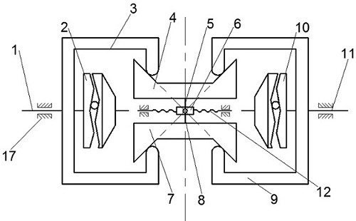
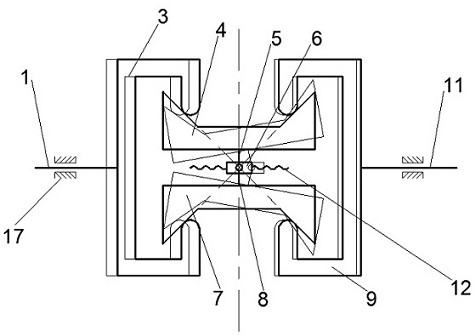
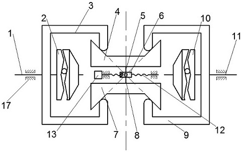
[0032] Such as figure 1 As shown, it is the transmission principle diagram of the present embodiment. The self-adaptive variable speed external cone-disk type non-spin traction type continuously variable transmission is composed of an input shaft 1, an input roller 3, an intermediate transmission component, an output shaft 11, an output roller 9 and a speed changer. Mechanism composition: an input end cam loading mechanism 2 is arranged between the input shaft 1 and the input roller 3, an output end cam loading mechanism 10 is arranged between the output shaft 11 and the output roller 9, and the input shaft 1 and the output shaft 11 Coaxial installation; the intermediate transmission part is composed of upper and lower groups of symmetrically placed upper transmission cones 4 and lower transmission cones 7, upper shifting rocker 5, lower shifting rocker 8 and shifting sleeve 6, the upper transmission The cone 4 and the lower transmission cone 7 are respectively installed on th...
Embodiment 2
[0035] Such as figure 1 As shown, it is the transmission principle diagram of the present embodiment. The self-adaptive variable speed external cone-disk type non-spin traction type continuously variable transmission is composed of an input shaft 1, an input roller 3, an intermediate transmission component, an output shaft 11, an output roller 9 and a speed changer. Mechanism composition: an input end cam loading mechanism 2 is arranged between the input shaft 1 and the input roller 3, an output end cam loading mechanism 10 is arranged between the output shaft 11 and the output roller 9, and the input shaft 1 and the output shaft 11 Coaxial installation; the intermediate transmission part is composed of upper and lower groups of symmetrically placed upper transmission cones 4 and lower transmission cones 7, upper shifting rocker 5, lower shifting rocker 8 and shifting sleeve 6, the upper transmission The cone 4 and the lower transmission cone 7 are respectively installed on th...
PUM
 Abstract
Description
Claims
Application Information
 - R&D
- Intellectual Property
- Life Sciences
- Materials
- Tech Scout
- Unparalleled Data Quality
- Higher Quality Content
- 60% Fewer Hallucinations
Browse by: Latest US Patents, China's latest patents, Technical Efficacy Thesaurus, Application Domain, Technology Topic, Popular Technical Reports.
© 2025 PatSnap. All rights reserved.Legal|Privacy policy|Modern Slavery Act Transparency Statement|Sitemap|About US| Contact US: help@patsnap.com


