Pneumatic test experiment table with pipeline management structure

A technology for testing experiments and test benches, applied in pump testing, mechanical equipment, machines/engines, etc., can solve the problems of resource waste, time consumption, oil pollution test benches, etc., to facilitate disassembly and replacement, and reduce shaking frequency Effect

Inactive Publication Date: 2022-01-04
安徽声谷智能科技有限公司
View PDF0 Cites 0 Cited by
  • Summary
  • Abstract
  • Description
  • Claims
  • Application Information

AI Technical Summary

Problems solved by technology

[0004] The purpose of the present invention is to provide a pneumatic test bench equipped with a pipeline management structure to solve the problem that the oil collection tank proposed in the above background technology will shake with the weight it bears, so more oil will flow out and pollute the test bench Internally, the impurities in the oil cannot be filtered and cleaned, and mixed with the used oil, so that resources are wasted, the oil cannot be recycled, and it takes a lot of time to clean impurities, which is time-consuming and labor-intensive. question

Method used


Image

  • Pneumatic test experiment table with pipeline management structure
  • Pneumatic test experiment table with pipeline management structure
  • Pneumatic test experiment table with pipeline management structure

Examples


Embodiment 1

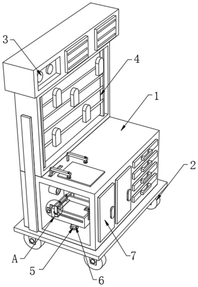
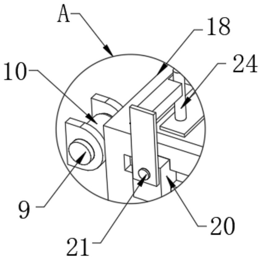
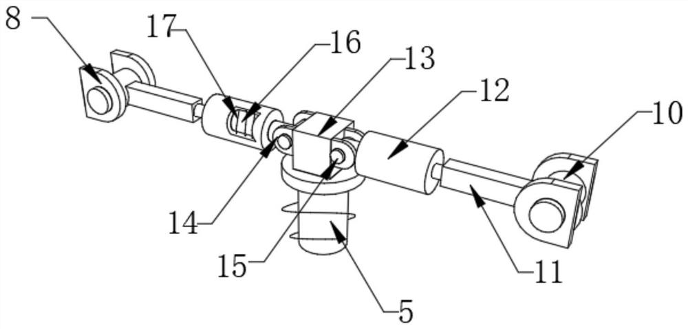
[0029] Such as figure 1 , figure 2 , image 3 and Figure 4 As shown, including the test bench body 1, universal wheels 2, control panel 3 and movable box 4, the four corners of the bottom end of the test bench body 1 are fixed with universal wheels 2, and the top side of the test bench body 1 is A control panel 3 is fixedly installed, and a movable box 4 is movably installed on the other side of the top of the test bench body 1. The bottom end of the test bench body 1 is interspersed with a movable column 5, and a first spring 6 is wound outside the movable column 5. Two tool cabinets 7 are fixedly installed on the front of the test bench body 1, two first connecting frames 8 are fixedly installed on both sides of the inner wall of the test bench body 1, and a support block 13 is fixedly installed on the top of the movable column 5, and the support block 13 Two support plates 14 are fixedly installed on both sides of the two support plates 14, and a second rotating shaft ...

Embodiment 2

[0032] On the basis of Embodiment 1, such as Figure 4 , Figure 5 and Figure 6 As shown, two fixed plates 26 are fixedly installed on the front of the oil collecting tank 18, and the tops of the two fixed plates 26 are interspersed with fixed shafts 27, and one end of the two fixed shafts 27 is movably sleeved with a clamping plate 28. The top of the table body 1 is provided with two movable slots, and one side of the installation box 33 is provided with a plurality of tube slots 34, the inside of the two movable slots is slidably equipped with an auxiliary plate 29, and the outside of the two telescopic columns 16 is wound with Both sides of the second spring 17 and the oil collection tank 18 are provided with chute 19, and the tops of the two auxiliary plates 29 are hinged with an extension frame 30, and the tops of the two extension frames 30 are interspersed with magnets 31. The present invention provides chute 19, slide block 20, stop post 24, clamping plate 28, magne...


PUM


Abstract

The invention relates to the technical field of pneumatic test experiment tables with pipeline management structures, in particular to a pneumatic test experiment table with a pipeline management structure, which comprises an experiment table body, universal wheels, a control panel and a movable box, universal wheels are fixedly mounted at the four corners of the bottom end of the experiment table body, a control panel is fixedly mounted on one side of the top end of the experiment table body, and a movable box is movably mounted on the other side of the top end of the experiment table body. The table is provided with a first connecting frame, a telescopic column, a connecting plate, a movable column, a supporting plate and a first spring, the movable columns move in the experiment table body in a penetrating mode through the first springs wound outside, the movable columns can control the swing time of the two movable frames not to be too long, and therefore the swing frequency of the oil collecting tank installed at the top end of the supporting block is reduced, and the situation that oil leaked in a pipeline flows into the oil collecting tank and shakes and flows out is avoided.

Description

technical field [0001] The invention relates to the technical field of a pneumatic test bench with a pipeline management structure, in particular to a pneumatic test bench with a pipeline management structure. Background technique [0002] With the development and application of hydraulic transmission technology, the new hydraulic experimental equipment developed, its control accuracy and rapid response are much higher than ordinary hydraulic transmission experimental equipment. The static and dynamic performance tests allow students to intuitively understand the performance and main technical parameters of the core components of the hydraulic system. Participating in the test means working on the pneumatic test bench. Composed of components such as control devices and programmable logic controllers (PLC), the experimental pneumatic components adopt a movable lever structure, and the four-way experimental assembly is fast and convenient; the experimental circuit has high def...

Claims


Application Information

Patent Timeline
Patent Type & Authority Applications(China)
IPC IPC(8): G09B25/00F04B51/00
CPCG09B25/00F04B51/00
Inventor 李之兵李云龙李之美
Owner 安徽声谷智能科技有限公司
Why Eureka
Try Eureka