Phase control valve with hydraulic recovery structure

A phase control, hydraulic technology, applied in valve devices, combustion engines, machines/engines, etc., can solve the problems of high consumption, high oil volume, low pump oil pressure, etc., to reduce supplementary consumption and improve valve phase adjustment speed. Effect

Active Publication Date: 2022-01-07
ZHEJIANG FUJIEDE AUTOMOTIVE SYST CO LTD
View PDF5 Cites 0 Cited by
  • Summary
  • Abstract
  • Description
  • Claims
  • Application Information

AI Technical Summary

Problems solved by technology

[0003] The general oil control valve inputs the oil pressure through the oil pump, switches it to the advance angle or delay angle oil chamber of the phaser for adjustment, and the oil in the chamber on the other side is discharged to the engine oil pan through the oil control valve. This process It will consume more engine oil and put a greater burden on the oil pump
When the engine speed is low, the corresponding pump oil pressure is also low, and the flow rate is also small. The speed of valve phase adjustment will be affected, resulting in slow response, which will affect the switching efficiency and switching timeliness.

Method used


Image

  • Phase control valve with hydraulic recovery structure
  • Phase control valve with hydraulic recovery structure
  • Phase control valve with hydraulic recovery structure

Examples


Embodiment Construction

[0027] The following will clearly and completely describe the technical solutions in the embodiments of the present invention with reference to the accompanying drawings in the embodiments of the present invention. Obviously, the described embodiments are only some of the embodiments of the present invention, not all of them. Based on the embodiments of the present invention, all other embodiments obtained by persons of ordinary skill in the art without making creative efforts belong to the protection scope of the present invention.

[0028] In the description of the present invention, it should be noted that the terms "upper", "lower", "inner", "outer", "front end", "rear end", "both ends", "one end", "another end" The orientation or positional relationship indicated by etc. is based on the orientation or positional relationship shown in the drawings, and is only for the convenience of describing the present invention and simplifying the description, rather than indicating or ...


PUM


Abstract

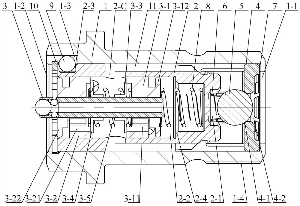
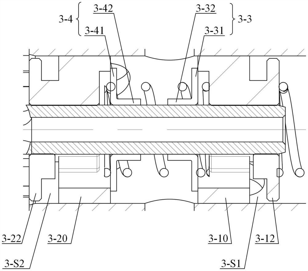
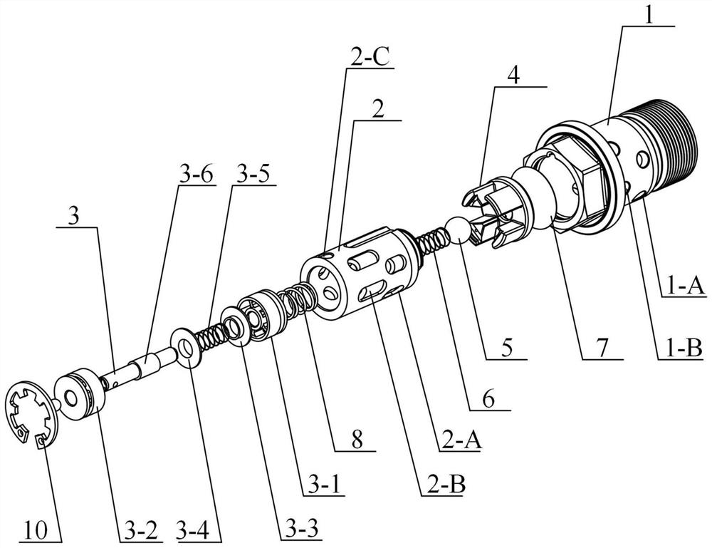
The invention provides a phase control valve with a hydraulic recovery structure. A recovery spring (3-5) is arranged between a first valve plate (3-3) and a second valve plate (3-4), and the first valve plate (3-3) and the second valve plate sleeve a reversing rod (3) and can axially move relative to the reversing rod (3); a first recovery oil channel (3-11) is arranged in a first valve block (3-1), a second recovery oil channel (3-21) is arranged in a second valve block (3-2), the first recovery oil channel (3-11) and a second recovery oil channel (3-21) communicate with an inner cavity of a valve sleeve (2), engine oil to be discharged originally is recovered and used in a control valve, engine oil consumption is reduced, the valve phase adjusting speed of the engine under the low-rotating-speed working condition can be effectively increased.

Description

technical field [0001] The invention relates to the technical field of internal combustion engine variable valve timing adjustment technology, in particular to a phase control valve with a hydraulic recovery structure. Background technique [0002] Variable valve timing adjustment technology refers to changing the overlapping angle of the intake and exhaust valves by controlling the opening angle of the intake and exhaust valves of the internal combustion engine under specific engine conditions, thereby increasing the intake charge and Efficiency, to better organize the intake vortex, adjust the cylinder explosion pressure and residual exhaust gas volume, and finally obtain comprehensive performance improvements such as engine power, torque, emissions, and fuel economy. [0003] The general oil control valve inputs the oil pressure through the oil pump, switches it to the advance angle or delay angle oil chamber of the phaser for adjustment, and the oil in the chamber on the...

Claims


Application Information

Patent Timeline
Patent Type & Authority Applications(China)
IPC IPC(8): F01L1/344
CPCF01L1/3442F01L2001/34426F01L2001/3444F01L2001/34423Y02T10/12
Inventor 王俊杰王锦富李建全毕峰源杨寅黄少春
Owner ZHEJIANG FUJIEDE AUTOMOTIVE SYST CO LTD
Why Eureka
Try Eureka