Anti-pressure-relief energy-saving gas compressor

A gas compressor and energy-saving technology, applied in the field of air pressure components, can solve the problem of serious energy consumption of gas compressors, and achieve the effects of improving the fixing effect, expanding the cross-sectional area, and improving the sealing effect.

Pending Publication Date: 2022-01-07
谭浩
View PDF8 Cites 0 Cited by
  • Summary
  • Abstract
  • Description
  • Claims
  • Application Information

AI Technical Summary

Problems solved by technology

[0005] Aiming at the deficiencies of the prior art, the present invention provides an anti-pressure release and energy-saving gas compressor, which solves the problem of serious energy consumption of the gas compressor

Method used


Image

  • Anti-pressure-relief energy-saving gas compressor
  • Anti-pressure-relief energy-saving gas compressor
  • Anti-pressure-relief energy-saving gas compressor

Examples


Embodiment 1

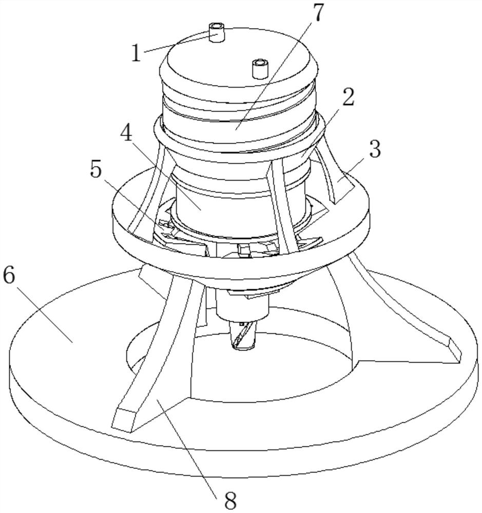
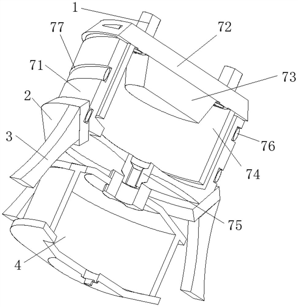
[0035] like Figure 1-2 As shown, the present invention provides a technical solution: an anti-pressure release energy-saving gas compressor, including a base ring 6, the top of the base ring 6 is fixedly connected to a support rod 8, and the top of the support rod 8 is fixedly connected to There is an anti-pressure relief device 5, and the middle position of the top of the anti-pressure relief device 5 is provided with a pressure storage tank 4, and the top of the pressure storage tank 4 is fixedly connected with a pressurizing device 7, and the top of the pressurizing device 7 The air intake pipe 1 is fixedly connected, and the outer surface of the pressurizing device 7 is fixedly connected with a fixed ring plate 2, and the bottom of the fixed ring plate 2 is fixedly connected to the upper surface of the pressure relief device 5 through the upper support frame 3. The pressurizing device 7 includes an elastic slide bar 76 and a rotating pressurizing plate 72, the bottom of t...

Embodiment 2

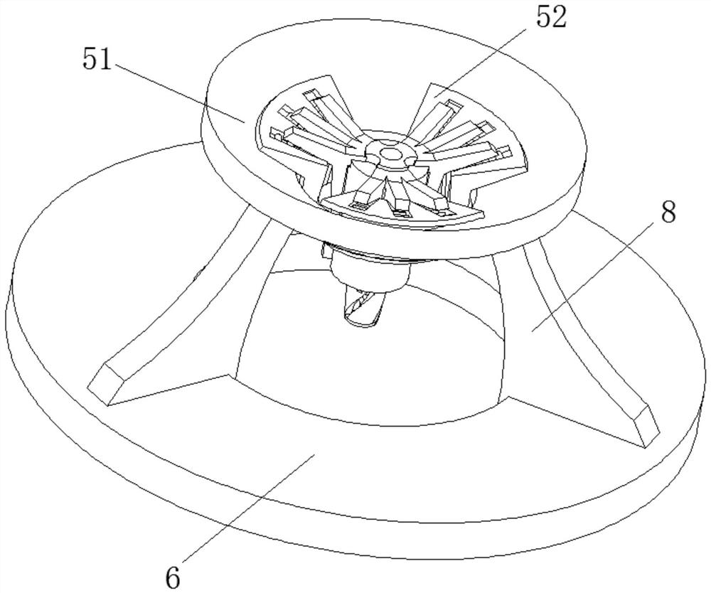
[0042] like Figure 3-5 As shown, on the basis of Embodiment 1, the present invention provides a technical solution: the anti-pressure relief device 5 includes a pressure relief pipe chamber 56, and the side of the upper surface of the pressure relief pipe chamber 56 is fixedly connected with a plastic bifurcation Block 54, the middle of the top of the pressure relief pipe warehouse 56 is fixedly connected with a one-way air valve device 53;

[0043] A seal ring 57 is fixedly connected to the inner wall of the bottom of the pressure relief pipe chamber 56, and an air outlet device 58 is fixedly connected to the inside of the seal ring 57, and an anti-extrusion ring 51 is fixedly connected to the top of the support rod 8. A side extrusion block 52 is fixedly connected to the inside of the anti-extrusion ring 51 .

[0044] The depression on the upper surface of the side extrusion block 52 is provided with a friction block 55, the outer surface of the friction block 55 is adapte...

Embodiment 3

[0051] like Figure 6-7 As shown, on the basis of Embodiment 1 and Embodiment 2, the present invention provides a technical solution: the one-way air valve device 53 also includes an air valve block 531, and the outer surfaces of the air valve block 531 are respectively fixedly connected In the middle of the pressure relief pipe warehouse 56 and the top of the pressure storage tank 4, the transmission rod 533 runs through the air valve block 531 and extends to the outside, and the end of the transmission rod 533 away from the double-layer airtight plate 534 is fixedly connected to the outer top plate 532.

[0052] The bottom between the opposite surfaces of the double-layer airtight plates 534 is provided with a central groove 535, and the top between the opposite surfaces of the double-layer airtight plates 534 is fixedly connected with a plug cover 536, and the upper surface of the plug cover 536 is in contact with the The central groove 535 fits. When the gas valve block ...


PUM


Abstract

The invention discloses an anti-pressure-relief energy-saving gas compressor which comprises a base ring, the top of the base ring is fixedly connected with a supporting rod, the top of the supporting rod is fixedly connected with an anti-pressure-relief device, the middle position of the top of the anti-pressure-relief device is sleeved with a pressure storage box, and the top of the pressure storage box is fixedly connected with a pressurizing device; and the top of the pressurizing device is fixedly connected with an air inlet pipe, the outer surface of the pressurizing device is fixedly connected with a fixing ring plate, the bottom of the fixing ring plate is fixedly connected to the upper surface of the pressure relief preventing device through an upper supporting frame, and the pressurizing device comprises an elastic sliding rod and a rotary pressurizing plate. According to the anti-pressure-relief energy-saving gas compressor, the rotary pressurizing plate rotates when the gas compressor works, a pressurizing block can pressurize internal gas under the action of downward rotation, the pressurizing effect is stable, and the situation that the gas causes too large pressure on the inner wall of the pressurizing device during powerful pressurizing, and consequently hard damage is caused is prevented.

Description

technical field [0001] The invention relates to the technical field of pneumatic components, in particular to an anti-pressure leakage and energy-saving gas compressor. Background technique [0002] A gas compressor is a power device that converts mechanical energy into gas pressure energy. It is often used to provide gas power for pneumatic tools. It is also commonly used for pressure delivery of oxygen, hydrogen, ammonia, natural gas, coke, etc. Furnace gas, inert gas and other media. [0003] In the existing gas compressors, the gas compressor is used to compress the gas vertically, which consumes a lot of energy; after a long time, the gas under high pressure will always be released from the gas valve, causing the pressure value of the compressed gas to drop and waste resource. Contents of the invention [0004] (1) Solved technical problems [0005] Aiming at the deficiencies of the prior art, the present invention provides a pressure relief and energy-saving gas c...

Claims


Application Information

Patent Timeline
Patent Type & Authority Applications(China)
IPC IPC(8): F04B37/12F04B39/00F04B39/10F04B39/12
CPCF04B37/12F04B39/10F04B39/123F04B39/12F04B39/0005F04B39/121Y02P20/10
Inventor 谭浩
Owner 谭浩
Why Eureka
Try Eureka