
Fluid connector

A connector and fluid technology, applied in the direction of couplings, mechanical equipment, etc., can solve problems such as fluid medium leakage

Active Publication Date: 2022-01-07
GUIZHOU SPACE APPLIANCE CO LTD
View PDF13 Cites 0 Cited by
  • Summary
  • Abstract
  • Description
  • Claims
  • Application Information

AI Technical Summary

Problems solved by technology

However, there is an air entrainment gap between the first diversion hole and the third diversion hole of the above-mentioned fluid connector. In the mated state, the gap is exposed to the fluid medium, and the air entrainment gap will be filled with fluid medium. After the connector is separated, The air-entrapped gap communicates with the external environment, causing the fluid medium in it to be carried out to form a leak

Method used


Image

  • Fluid connector
  • Fluid connector
  • Fluid connector

Examples


Embodiment Construction

[0024]The technical solution of the present invention is further described below, but the scope of protection is not limited to the description.

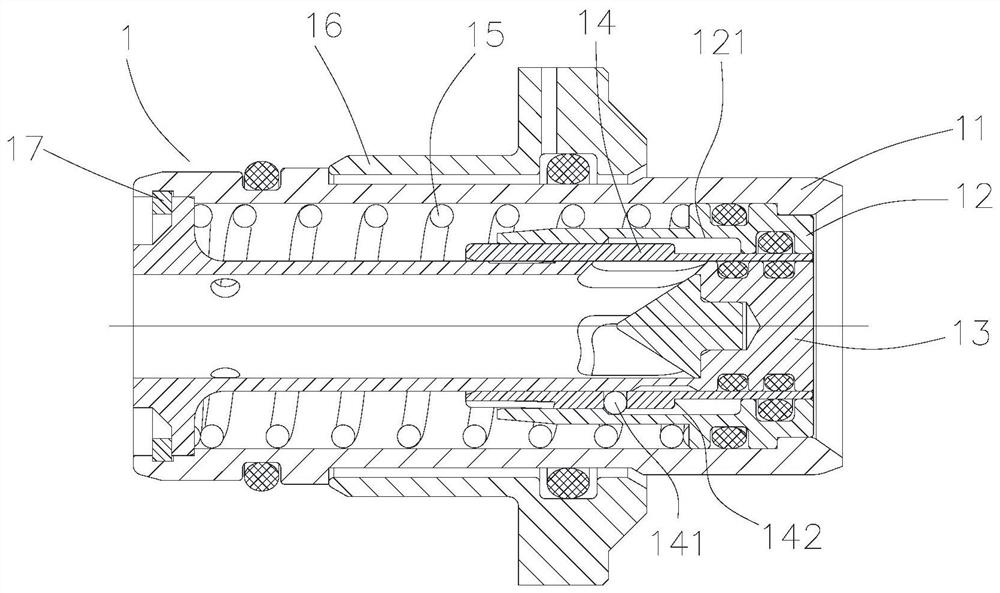
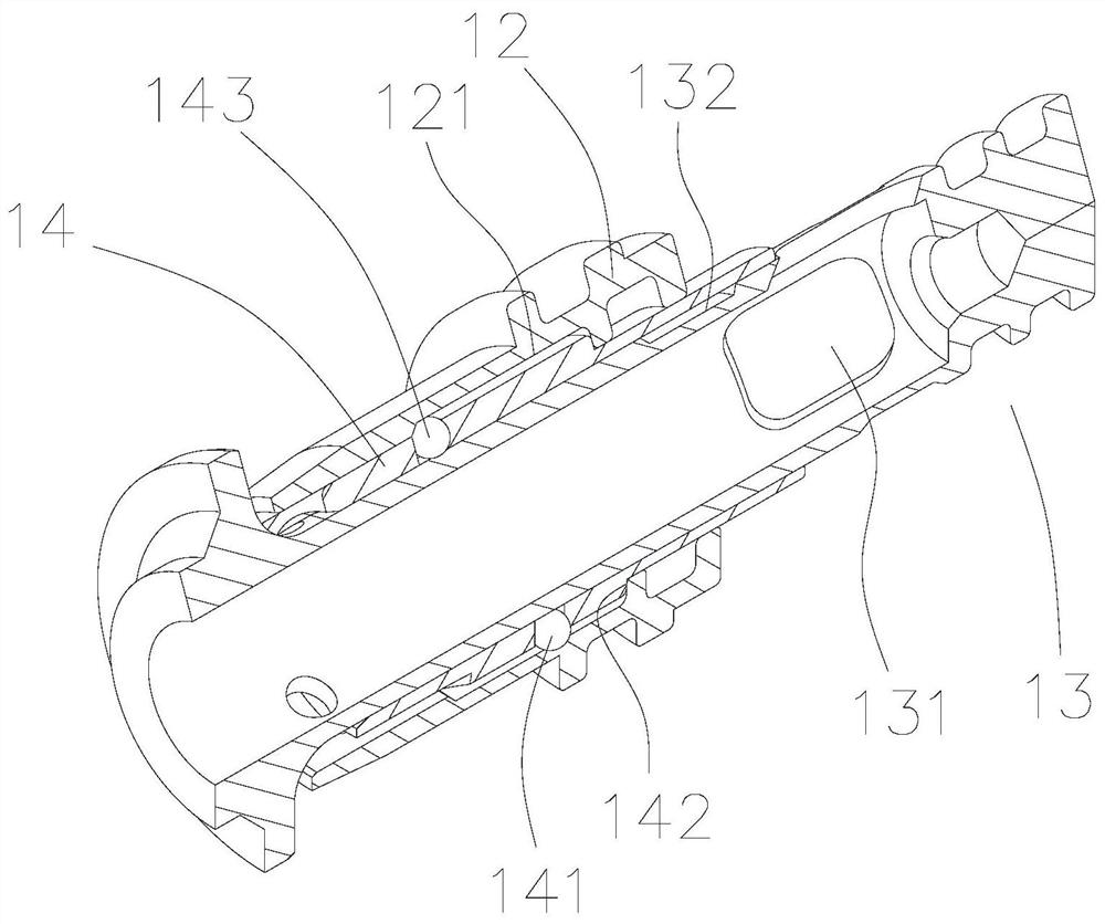
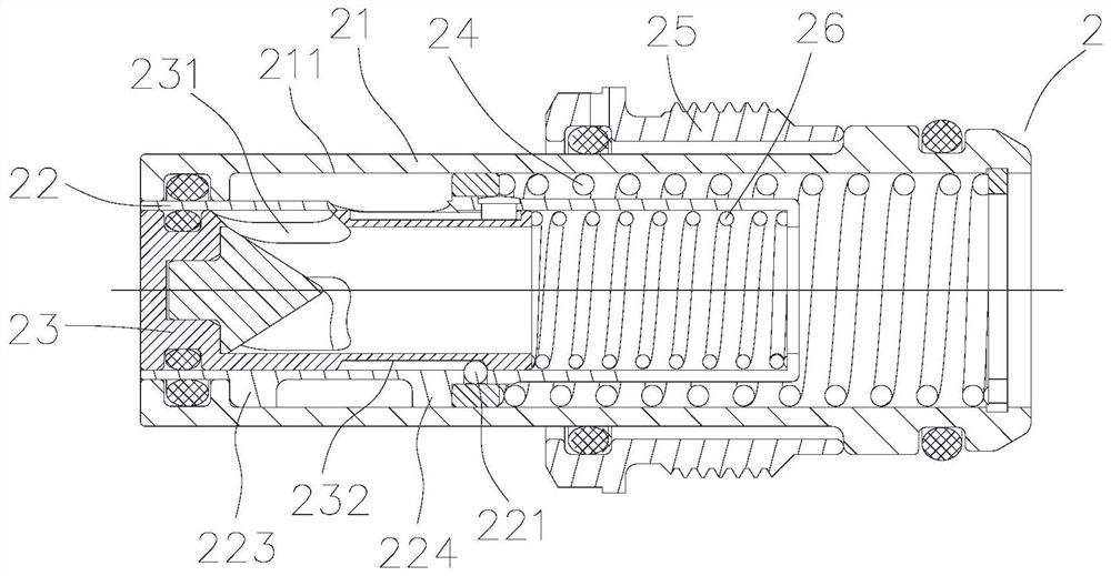
[0025] Such as Figure 1 to Figure 5 As shown, a fluid connector includes a female connector 1 and a male connector 2 that fits into the female connector 1. The female connector 1 includes a female connector sealing sleeve 12 that is slid from outside to inside and a female connector limit sleeve. 14 and the female joint spool 13, the first elastic mechanism and the first axial limit mechanism are arranged in the female joint 1 to make the female joint sealing sleeve 12, the female joint limit sleeve 14 flush with the butt end surface of the female joint spool 13, The internal channel of the female joint spool 13 has a first window 131 in the radial direction on the side, and the female joint limit sleeve 14 blocks the first window 131. The male joint 2 includes a male joint housing 21, a male joint housing 21, and a male joint that...


PUM


Abstract

The invention provides a fluid connector. The fluid joint comprises a female joint and a male joint matched with the female joint in an inserted manner, the female joint comprises a female joint sealing sleeve, a female joint limiting sleeve and a female joint valve element which sequentially sleeve in a sliding and sealing manner from outside to inside, and a first window is formed in the side face of an inner channel of the female joint valve element in the radial direction; and the female joint limiting sleeve shields the first window, the male joint comprises a male joint shell, a male joint limiting sleeve and a male joint valve element which sequentially sleeve in a sliding and sealing manner from outside to inside, a second window is formed in the side face of an inner channel of the male joint valve element in the radial direction, and the male joint limiting sleeve shields the second window. According to the fluid connector, in the plugging process, an air clamping gap and a flow channel are always in an isolated state, so that the problem that because the air clamping gap on the plugging face of an existing fluid joint is exposed in a fluid medium, leakage exists in the plugging process is solved.

Description

technical field [0001] The invention belongs to the field of connectors, in particular to a fluid connector. Background technique [0002] Liquid cooling technology has been widely used in aviation, aerospace, electronics, ships, communications and other fields. The fluid joint is a key component of the cooling fluid transmission between the liquid cooling module and the chassis. During the maintenance or debugging process of the liquid cooling system In the process, the cooling system often needs to be maintained, and the fluid joints on the equipment need to be plugged and unplugged. During the plugging process, the joints are required to maintain a good sealing effect to avoid the impact of cooling medium leakage on the system. [0003] The Chinese patent with the publication number CN105351652A discloses a fluid connector, which includes a socket and a plug; the plug has a first diversion hole, and the first diversion hole has a first inner convex ring, a first snap ring...

Claims


Application Information

Patent Timeline
IPC IPC(8): F16L37/36F16L37/32F16L37/138
CPCF16L37/36F16L37/32F16L37/138
Inventor 肖应富石良昌陈谋钦刘贲周斌王飞刘晰
Owner GUIZHOU SPACE APPLIANCE CO LTD
Learn More