Vibration mechanism and high-precision locating charging vibration device

A technology of vibrating mechanism and vibrating device, which is applied in the direction of weapon accessories, ammunition, offensive equipment, etc., can solve the problem that different materials cannot obtain the best vibration effect, achieve good vibration effect, ensure positioning accuracy, and ensure stability

Pending Publication Date: 2022-01-07
中国兵器装备集团自动化研究所有限公司
View PDF7 Cites 0 Cited by
  • Summary
  • Abstract
  • Description
  • Claims
  • Application Information

AI Technical Summary

Problems solved by technology

[0003] The technical problem to be solved by the present invention is how to make the vibration amplitude of the vibrating table easy to adjust. The purpose is to provide a vibrating mechanism and a high-pr

Method used


Image

  • Vibration mechanism and high-precision locating charging vibration device
  • Vibration mechanism and high-precision locating charging vibration device
  • Vibration mechanism and high-precision locating charging vibration device

Examples


Example Embodiment

[0035] Example

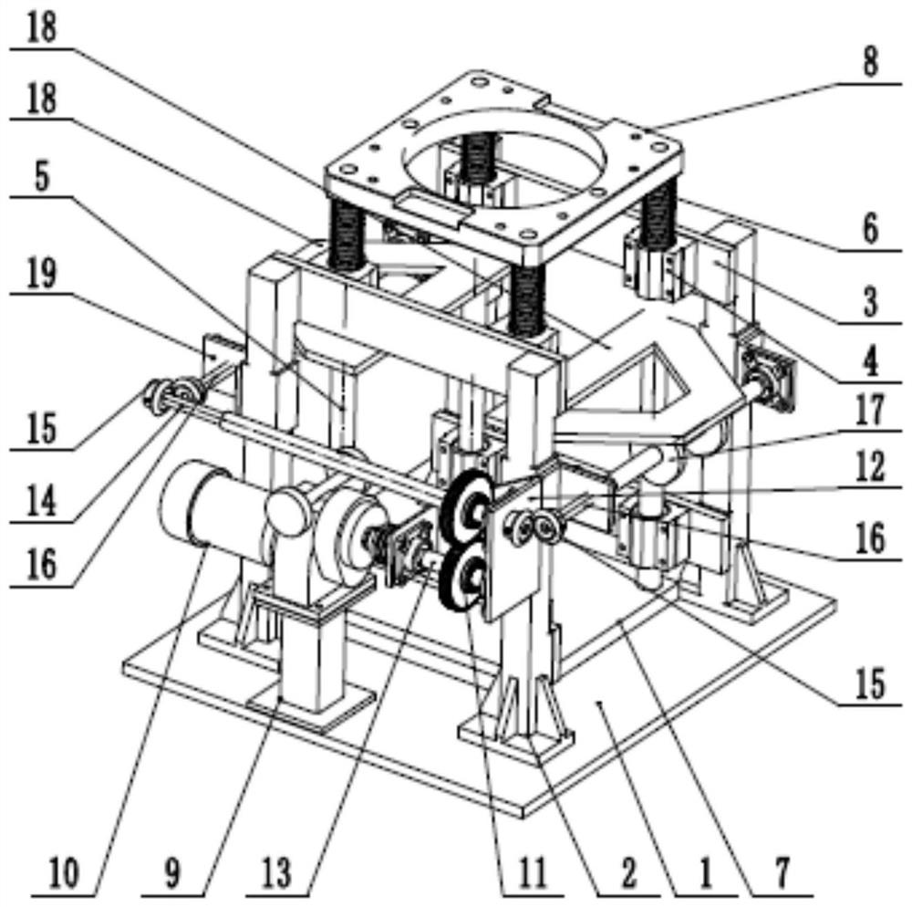
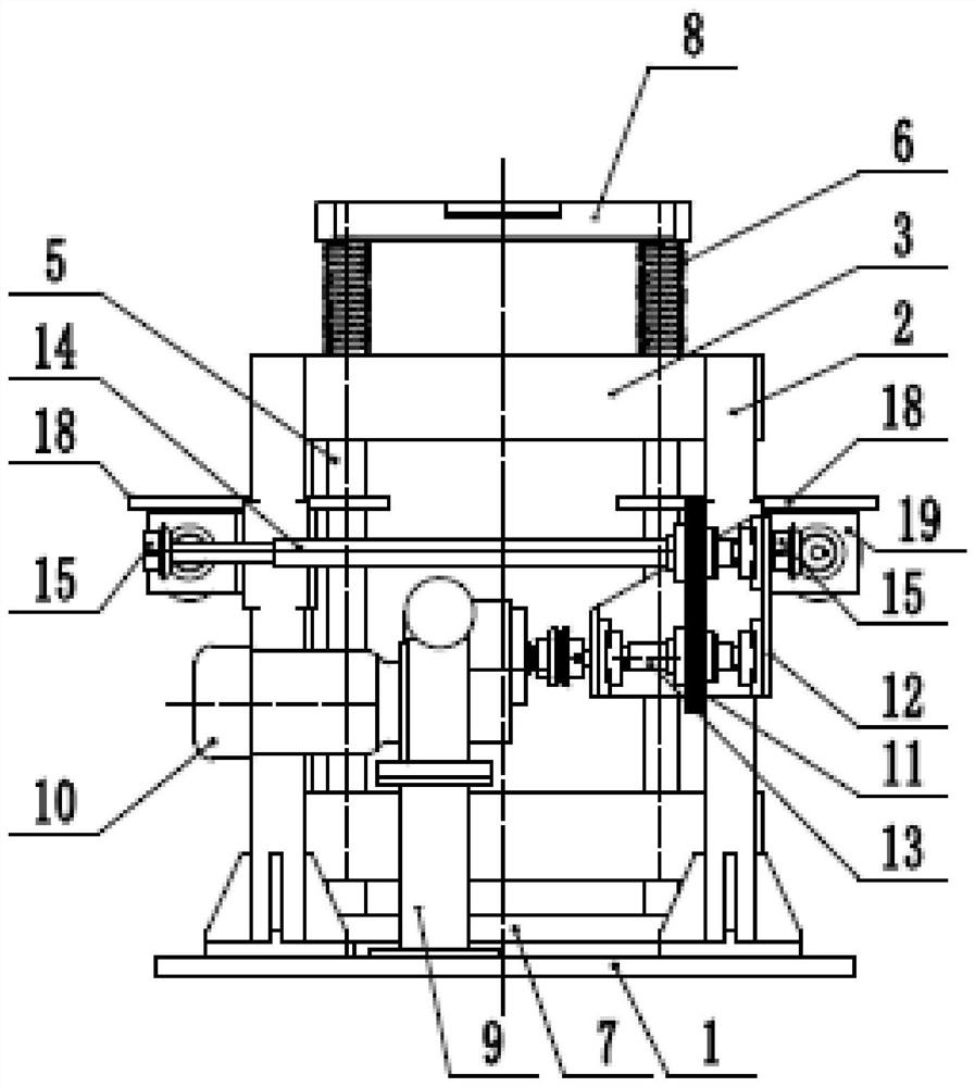
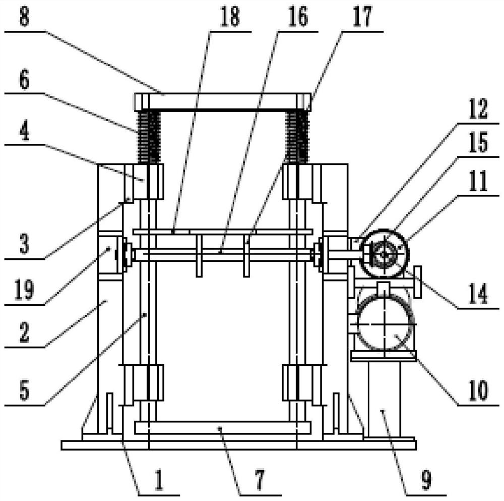
[0036] A vibrating mechanism, see figure 1 , including: a guide shaft 5 for connecting with the vibration platform 8; a controlled 18, which is detachably and fixedly connected to the guide shaft 5; a cam 16, which is provided on a On the other hand, the cam 16 is also configured with a power source; in the working state, when the cam 16 is in a controlled state driven by the power source, the cam 16 can contact the controlled 18 to make the controlled 18 moves along the axial direction of the guide shaft 5 .

[0037]Specifically, the guide shaft 5 is in the shape of a strip, and the cross-sectional shape of the guide shaft 5 in the direction perpendicular to the axial direction may not be limited, such as commonly used circle, square, triangle, ellipse, polygon, etc. It adopts a circular shape, and the detachable fixed connection between the controlled 18 and the guide shaft 5 can be implemented by some conventional methods in the prior art, such as connect...


PUM


Abstract

The invention discloses a vibration mechanism and a high-precision locating charging vibration device. The problem that different materials cannot achieve the optimal vibration effect due to a fixed amplitude of an existing vibration platform is solved. The vibration mechanism comprises a guide shaft connected with a vibration platform, a controlled part detachably and fixedly connected with the guide shaft, and a cam arranged on one side of the controlled part and further provided with a power source. In the working state, when the cam is driven by the power source to be in the controlled state, the cam can be in contact with the controlled part so that the controlled part is moved in the axial direction of the guide shaft. The vibration mechanism has the advantages of being adjustable in amplitude, convenient in adjustment, simple in structure, small in influence on overall vibration and the like.

Description

technical field [0001] The invention relates to the technical field of pyrotechnics, in particular to a vibration mechanism and a high-precision positioning charging vibration device. Background technique [0002] In the process of charging pyrotechnics, vibration is a work link that cannot be ignored, and it determines the effect of charging. At present, the corresponding charging and vibrating devices generally use the method of placing tooling on the vibrating table to carry out corresponding operations, but this method has disadvantages: the amplitude of the corresponding vibrating table is fixed, which is not conducive to realizing the operation of different materials under the optimal parameter state, affecting quality. Contents of the invention [0003] The technical problem to be solved by the present invention is how to make the vibration amplitude of the vibration table easy to adjust. The purpose is to provide a vibration mechanism and a high-precision position...

Claims


Application Information

Patent Timeline
IPC IPC(8): F42B33/02
CPCF42B33/0257
Inventor 余瑶杨治林郭进勇黄求安李昂李全俊
Owner 中国兵器装备集团自动化研究所有限公司
Why Eureka
Try Eureka