Diffusion plate and forming method thereof

A diffusion plate, rectangular technology, applied in the field of diffusion plate and its formation, can solve the problem of reducing the uniformity of the picture, and achieve the effect of reducing the difficulty of splicing, reducing the possibility, and reducing the uniformity

Pending Publication Date: 2022-01-07
NINGBO SUNNY AUTOMOTIVE OPTECH
View PDF0 Cites 0 Cited by
  • Summary
  • Abstract
  • Description
  • Claims
  • Application Information

AI Technical Summary

Problems solved by technology

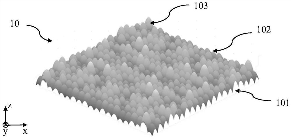
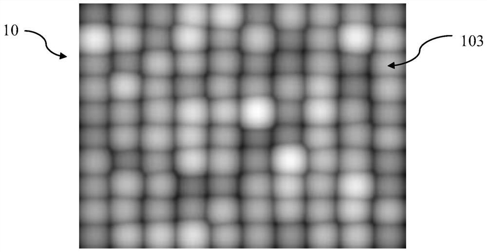
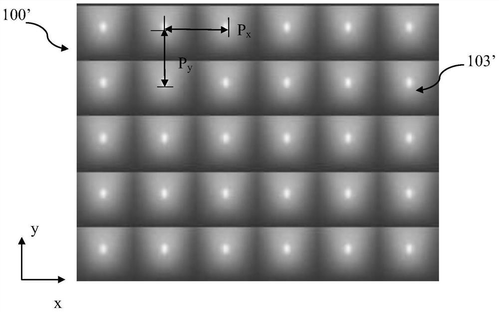
Conventional microstructure diffusers are composed of a series of identical microstructure arrays, which will produce speckle effect when applied to MEMS-PGU, which will cause obvious graininess in the projected picture and reduce the uniformity of the picture

Method used


Image

  • Diffusion plate and forming method thereof
  • Diffusion plate and forming method thereof
  • Diffusion plate and forming method thereof

Examples


Embodiment Construction

[0036] For a better understanding of the application, various aspects of the application will be described in more detail with reference to the accompanying drawings. It should be understood that these detailed descriptions are descriptions of exemplary embodiments of the application only, and are not intended to limit the scope of the application in any way. Throughout the specification, the same reference numerals refer to the same elements. The expression "and / or" includes any and all combinations of one or more of the associated listed items.

[0037] It should be noted that in this specification, expressions of first, second, third, etc. are only used to distinguish one feature from another, and do not represent any limitation on the features. Therefore, the first light-diffusing plate discussed hereinafter may also be referred to as the second light-diffusing plate without departing from the teachings of the present application. vice versa.

[0038] In this specificat...


PUM


Abstract

The invention provides a diffusion plate and a forming method thereof. The diffusion plate comprises a substrate and one or more micro-lens array units, the one or more micro-lens array units are arranged on the substrate and comprise a plurality of micro-lens units, and any edge of any one of the micro-lens array units is flat. According to the diffusion plate, the excellent spot dissipation effect can be achieved, and the diffusion plate is particularly suitable for design and machining of diffusion plates with large breadth.

Description

technical field [0001] The present application relates to the field of optical elements, and more specifically, to a diffuser plate and a forming method thereof. Background technique [0002] Devices such as Head Up Display (HUD), lidar, and driver assistance systems are more and more widely used, and these devices usually require the application of diffusers. The traditional diffuser can be frosted glass and other types of diffuser, but the microlens array diffuser is a new development direction. In the design and manufacture process of the microlens array diffuser plate, the shape of the microlens is better controllable than that of ground glass, and can more accurately realize the designed aspects such as the size of the diffusion angle, the uniformity of the light field, and the clarity. Effect. [0003] With the development of the HUD market, users have put forward higher and higher requirements for the resolution and definition of HUD products, and thus have higher a...

Claims


Application Information

Patent Timeline
IPC IPC(8): G02B5/02G02B3/00
CPCG02B5/0221G02B5/0268G02B3/0006G02B3/0012
Inventor 吴尚亮陈俊逸谢前森
Owner NINGBO SUNNY AUTOMOTIVE OPTECH
Why Eureka
Try Eureka