Self-pressing film antenna unfolding mechanism

An unfolding mechanism and self-compressing technology, which is applied in the direction of folding antennas, etc., can solve the problems of easy bending of the skeleton, failure to maintain the compressed state, instability, etc., and achieve the effect of ensuring reliability

Active Publication Date: 2022-01-07
CHINA ACADEMY OF SPACE TECHNOLOGY
View PDF6 Cites 1 Cited by
  • Summary
  • Abstract
  • Description
  • Claims
  • Application Information

AI Technical Summary

Problems solved by technology

[0005] The purpose of the present invention is to solve the problems in the prior art that in the process of unrolling and winding the film structure, the skeleton of the fixed film cannot be kept in a compressed state at all times, resulting in the skeleton being easily bent and unstable. Proposed self-compressing film antenna deployment mechanism

Method used


Image

  • Self-pressing film antenna unfolding mechanism
  • Self-pressing film antenna unfolding mechanism
  • Self-pressing film antenna unfolding mechanism

Examples


Embodiment 1

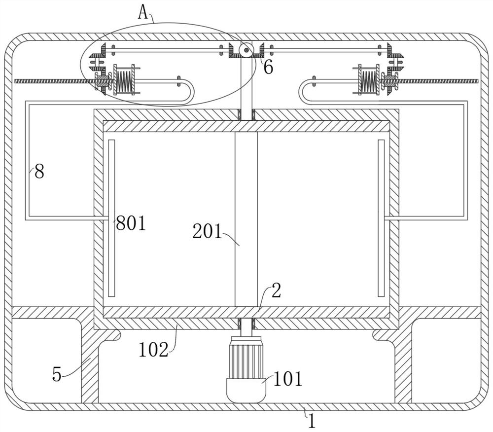
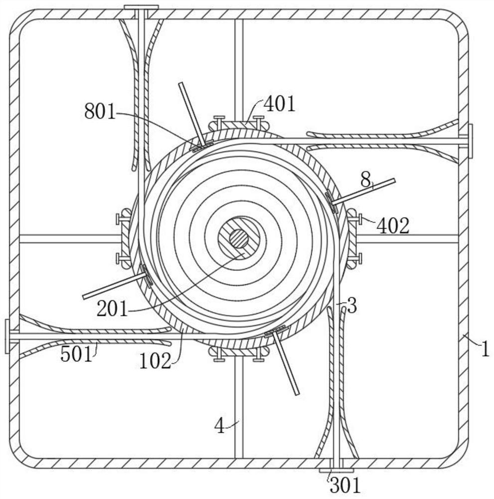
[0032] refer to Figure 1-8 , a self-compressing type film antenna deployment mechanism, including a box body 1 and a reel 102, the reel 102 is fixed in the box 1, the reel 102 is a hollow cylinder, and also includes: a motor 101, connected In the box body 1, the output end of the motor 101 is fixedly connected with the retracting shaft 201, and the retracting shaft 201 is located in the retracting drum 102 and is in line with the axis of the retracting drum 102; the extension arm 302, one end of the extension arm 302 is fixed On the retracting drum 102 and wound on the side wall of the retracting shaft 201, the film antenna body 3 is fixed on the skeleton formed by the extension arm 302; The skeleton composed of 302 runs through the retracting groove 202; the moving rod 8 is slidably connected to the side wall of the retracting drum 102, and the end of the moving rod 8 extending to the inside of the retracting drum 102 is connected with a compression device for maintaining th...

Embodiment 2

[0041] refer to Figure 1-8 , on the basis of Example 1, further,

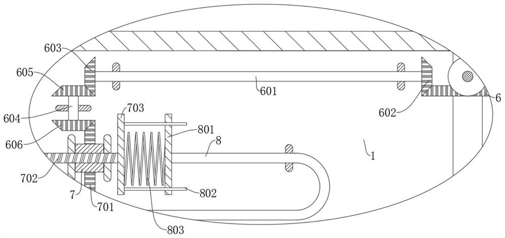
[0042] This embodiment discloses a pushing mechanism. The pushing mechanism includes a first rotating shaft 601 and a threaded rod 702. The first rotating shaft 601 is rotatably connected in the box body 1. The output end of the motor 101 extends out of the take-up shaft 201 and one end is fixedly connected with First bevel gear 6, one end of the first rotating shaft 601 is fixedly connected with the second bevel gear 602 meshed with the first bevel gear 6, and the end of the first rotating shaft 601 away from the second bevel gear 602 is fixedly connected with the third bevel gear 603 The second rotating shaft 604 and the threaded sleeve 7 are also rotatably connected in the box body 1, and one end of the second rotating shaft 604 is fixedly connected with the fourth bevel gear 605 meshed with the third bevel gear 603, and the second rotating shaft 604 is far away from the fourth bevel gear. One end of the g...

Embodiment 3

[0049] refer to Figure 1-8 , on the basis of Example 2, further,

[0050] The end of the threaded rod 702 close to the moving rod 8 is fixedly connected with the first voltage stabilizing plate 703, the end of the moving rod 8 away from the pressing part is fixedly connected with the second stabilizing plate 801, and the side wall of the first stabilizing plate 703 is fixedly connected with a guide The rod 802 and the guide rod 802 are slidably connected to the second pressure stabilizing disk 801 , and a voltage stabilizing spring 803 is also connected between the first voltage stabilizing disk 703 and the second pressure stabilizing disk 801 .

[0051] During the moving process of the threaded rod 702, the transmission force is transmitted to the moving rod 8 through the pressure stabilizing spring 803 to drive the moving rod 8 to move.

[0052] The elasticity of the pressure stabilizing spring 803 can effectively prevent the pressing part from moving suddenly and causing ...


PUM


Abstract

The invention discloses a self-pressing type film antenna unfolding mechanism, and belongs to the technical field of unfolding mechanisms. The self-pressing type film antenna unfolding mechanism comprises a box body and a winding cylinder, wherein the winding cylinder is fixed in the box body and is in a hollow cylinder shape; the self-pressing type film antenna unfolding mechanism further comprises a motor connected in the box body and extension arms; the output end of the motor is fixedly connected with a winding shaft, and the winding shaft is located in the winding cylinder and is collinear with the axis of the winding cylinder; and one end of each extension arm is fixed on the winding cylinder and is wound on the side wall of the winding shaft, and a film antenna body is fixed on a framework formed by the extension arms. When the self-pressing type film antenna unfolding mechanism works, pressing parts and the extension arms are uniquely corresponding to each other at each unfolding or winding moment, so that the motion states of the extension arms are relatively constant when the extension arms are unfolded and wound, the extension arms are prevented from expanding in the radial direction in the winding cylinder and even bending and becoming unstable is prevented, and the phenomenon that the film antenna body cannot be unfolded occurs.

Description

technical field [0001] The invention relates to the technical field of deployment mechanisms, in particular to a self-pressing film antenna deployment mechanism. Background technique [0002] Satellite film antenna is a new type of antenna. Different from traditional solid surface and cable net antennas, film antennas usually use microstrip patches etched on the surface of the film to form designed electromagnetic radiation characteristics. The satellite film antenna is folded into a smaller volume during the launch stage, and needs to be expanded into a larger aperture through the deployment mechanism when it is in orbit. Therefore, the deployment mechanism of the film antenna is a key component to ensure the normal operation of the satellite. [0003] With the progress of aerospace research in various countries, film antennas, including active phased array antennas and passive reflectarray antennas, have gradually become research hotspots. As a key component, the film ante...

Claims


Application Information

Patent Timeline
Patent Type & Authority Applications(China)
IPC IPC(8): H01Q1/08
CPCH01Q1/08
Inventor 李明健刘宇飞李萌黄小琦耿新宇李媛媛
Owner CHINA ACADEMY OF SPACE TECHNOLOGY
Why Eureka
Try Eureka