
Aircraft Fuel Temperature Sensor Mounting Kit

A temperature sensor and installation component technology, applied in the aviation field, can solve the problems of many openings in the fuel tank wall, affecting the structural strength, ignition source risk, etc., to avoid electromagnetic interference, reduce the number of openings, and stabilize the output of the resistance value.

Active Publication Date: 2022-07-19
COMAC +1
View PDF11 Cites 0 Cited by
  • Summary
  • Abstract
  • Description
  • Claims
  • Application Information

AI Technical Summary

Problems solved by technology

[0005] This installation method has the following disadvantages: the sensor is installed in the fuel tank, and it needs to enter the fuel tank for operation during installation and disassembly, which is inconvenient for maintenance; the sensor and cable are electrical equipment, and there is a risk of ignition source when installed in the fuel tank; to realize the sensor The number of openings in the structure is at least 5 (at least 4 rivet holes for fixing brackets on the inner floor of the fuel tank, and 1 hole for passing through the frame on the wall plate of the fuel tank)
[0007] This installation method has the following disadvantages: there are many openings on the fuel tank wall (at least 4 rivet holes on the fuel tank wall, and 1 frame hole on the fuel tank wall), which affects the structural strength; the sensor is an electrical device and is directly inserted into the fuel presents an ignition source risk in the fuel tank

Method used


Image

  • Aircraft Fuel Temperature Sensor Mounting Kit
  • Aircraft Fuel Temperature Sensor Mounting Kit
  • Aircraft Fuel Temperature Sensor Mounting Kit

Examples


Embodiment Construction

[0058]The specific embodiments of the present invention will be described below. It should be noted that, in the specific description of these embodiments, for the sake of brevity and conciseness, this specification may not describe all the features of the actual embodiments in detail. It should be understood that in the actual implementation process of any embodiment, just as in the process of any engineering project or design project, in order to achieve the developer's specific goals, in order to meet the system-related or business-related constraints, Often a variety of specific decisions are made, which also vary from one implementation to another. Furthermore, it will also be appreciated that while such development efforts may be complex and tedious, for those of ordinary skill in the art to which this disclosure pertains, the techniques disclosed in this disclosure will Some changes in design, manufacture or production based on the content are just conventional technica...


PUM


Abstract

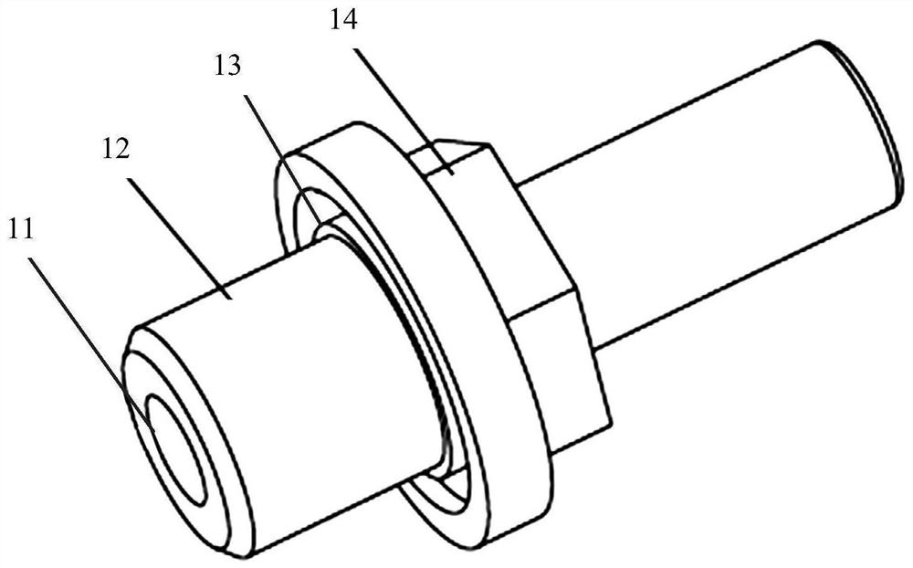
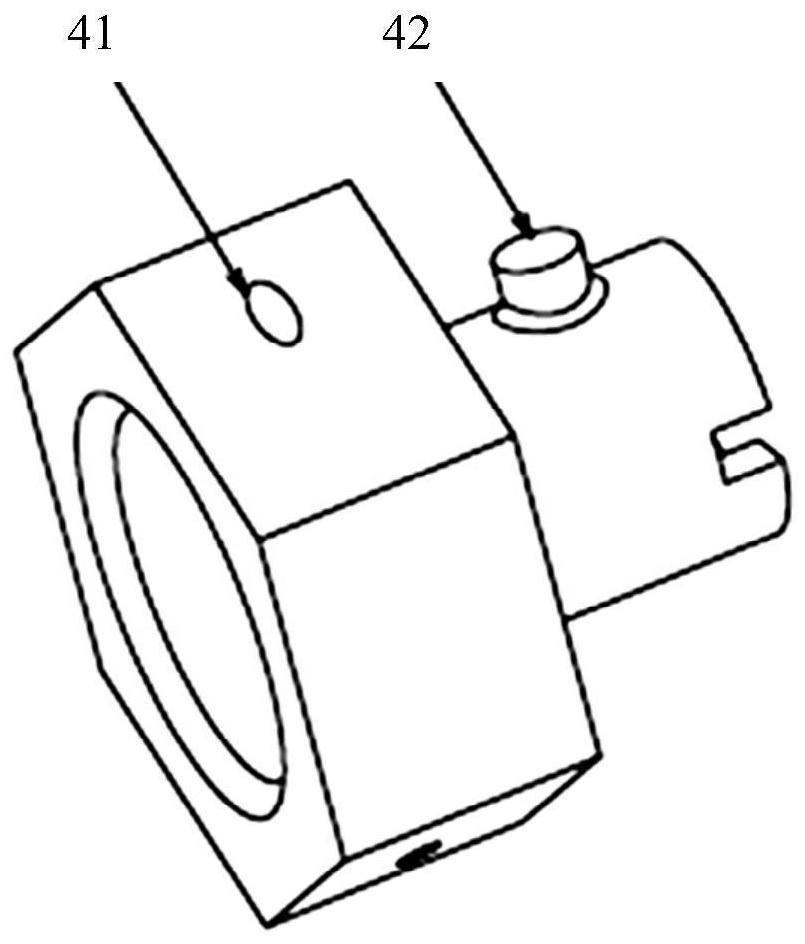
The present invention relates to an aircraft fuel temperature sensor mounting assembly. The aircraft fuel temperature sensor installation assembly includes an installation sleeve, a sealing ring, a customized nut, a temperature sensor, and an elastic part; the installation sleeve is provided with a blind hole for inserting the temperature sensor, an external thread part for engaging with the customized nut, and a It is used to place the groove of the sealing ring; the sealing ring is used to be fixed between the installation sleeve and the fuel tank wall to achieve fuel sealing; the temperature sensor is provided with a detection end and a slot; the custom nut is provided with a slot for fixing with the temperature sensor The assembled boss is used to realize the snap connection between the customized nut and the temperature sensor; the elastic part is sleeved outside the detection end of the temperature sensor to ensure that the snap connection between the customized nut and the temperature sensor will not loosen. According to the above technical scheme, the present invention can achieve the following beneficial technical effects: reducing the number of openings in the wall plate of the fuel tank, and avoiding the risk of ignition sources caused by the introduction of electrical equipment into the fuel tank.

Description

technical field [0001] The invention relates to the field of aviation technology, in particular to an aircraft fuel temperature sensor mounting assembly. Background technique [0002] Civil aircraft generally set a temperature indicator system in the fuel indicator system to measure and indicate the fuel temperature. When the sensor detects that the fuel temperature is lower than the minimum temperature set by the system, an alarm message will be generated to prompt the pilot to perform corresponding operations. [0003] The fuel temperature sensor is generally a resistance sensor. The sensor transmits the resistance value corresponding to the fuel temperature to the control center of the fuel system - the fuel computer. The fuel computer converts the resistance value into a temperature value and sends it to the avionics system. Warning system) page and fuel map page are displayed. The fuel computer will also compare the calculated fuel temperature value with the minimum fu...

Claims


Application Information

Patent Timeline
Patent Type & Authority Patents(China)
IPC IPC(8): G01K1/14
CPCG01K1/14
Inventor 宋志强唐慧娟张锦姜亮周宇穗
Owner COMAC
Learn More