System and method for detecting tracking performance of optical measurement equipment of movable platform

A technology of optical measurement equipment and detection system, which is applied in the field of tracking performance detection system of optical measurement equipment on moving platforms, and can solve problems such as inability to detect tracking performance, increased cycle and development costs, and blind spots in position

Active Publication Date: 2022-01-11
NO 63921 UNIT OF PLA
View PDF10 Cites 0 Cited by
  • Summary
  • Abstract
  • Description
  • Claims
  • Application Information

AI Technical Summary

Problems solved by technology

[0004] The tracking accuracy detection of the existing optical measurement equipment on the moving platform only detects and appraises the equipment under the condition of a static base. Due to the limited detection conditions, the detection requirements for tracking performance indicators are greatly reduced compared with the actual indicators under the moving platform, and cannot be completed. The detection and assessment of tracking performance in a real environment leads to the delivery of equipment with legacy problems. In the test task, once it is found that the equipment tracking performance indicators do not meet the requirements, it will be difficult to rectify the equipment and the cycle and development costs will increase significantly.
[0005] At this stage, the traditional ground-based detection device is used for the tracking performance detection of the optical measurement equipment of the moving platform. Since the ground-based detection device cannot truly simulate the motion characteristics of the moving platform, it is impossible to test the tracking performance in the actual application environment during the development stage of the optical measurement equipment.
In addition, ground-based detection devices generally use sin...

Method used


Image

  • System and method for detecting tracking performance of optical measurement equipment of movable platform
  • System and method for detecting tracking performance of optical measurement equipment of movable platform
  • System and method for detecting tracking performance of optical measurement equipment of movable platform

Examples


Embodiment 2

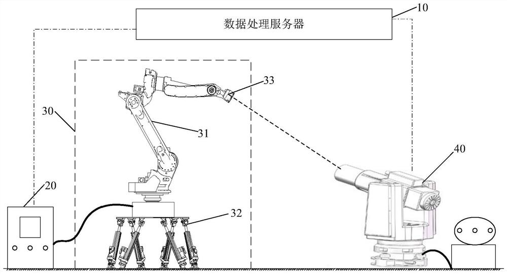
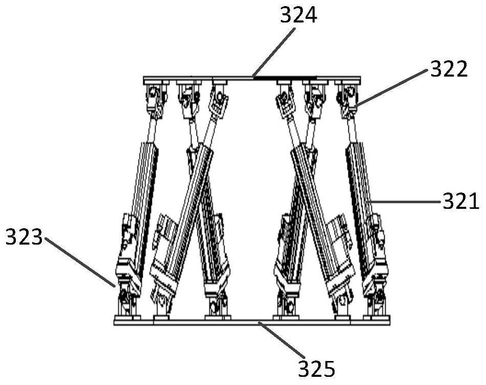
[0045] On the basis of Embodiment 1, this embodiment provides a specific implementation manner for the data processing server 10 to generate detection platform data. This embodiment takes a 6-DOF parallel robot as an example for illustration, including:

[0046] Determine the space velocity Jacobian matrix of a 6-DOF parallel robot.

[0047] According to the given value of the motion velocity of each joint in the 6-DOF parallel robot and the space velocity Jacobian matrix, the space velocity of each joint of the 6-DOF parallel robot is determined.

[0048] Among them, the space velocity Jacobian matrix of the 6-DOF parallel robot is determined by the following method:

[0049] Please refer to Figure 4 , Figure 4 It is a schematic diagram of the relationship between the motion variable and the coordinate system of a 6-DOF parallel robot. According to the screw theory and the spiral motion equation, the Jacobian matrix of the 6-DOF parallel robot is derived. express:

[00...

Embodiment 3

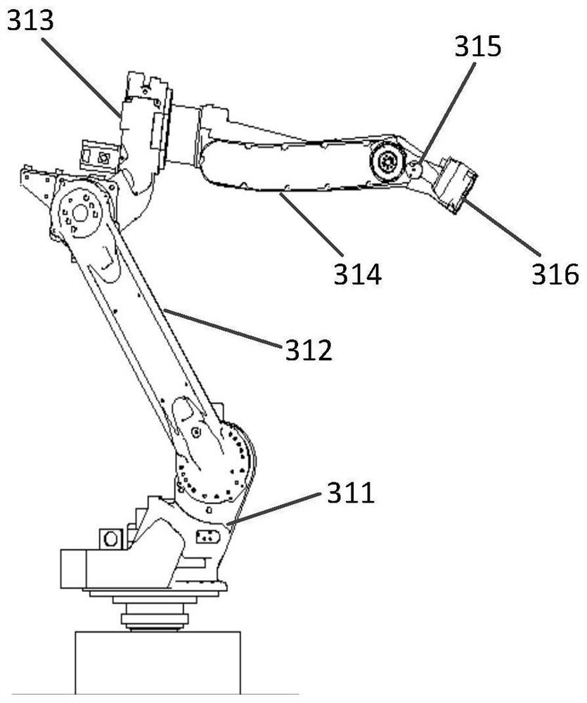
[0080] On the basis of Embodiment 1, this embodiment provides a specific implementation manner in which the data processing server 10 generates the motion data of the detection platform. This embodiment takes a 6-DOF serial manipulator as an example for illustration, including:

[0081] Determine the space velocity Jacobian matrix of a 6-DOF tandem manipulator.

[0082] According to the given value of the motion velocity of each joint in the 6-DOF series manipulator and the space velocity Jacobian matrix, the space velocity of each joint of the 6-DOF series manipulator is determined.

[0083] Among them, to determine the space velocity Jacobian matrix of the 6-DOF series manipulator, it needs to be determined in the following way:

[0084] Please refer to Figure 5 , Figure 5 It is a schematic diagram of the relationship between the motion variable and the coordinate system of the 6-DOF series manipulator. According to the screw theory, the connection coordinate system {M} ...

Embodiment 4

[0120] According to Embodiments 1, 2 and 3, it can be seen that the detection platform in the detection system provided by the embodiment of the present invention includes a 6-degree-of-freedom serial robot and a 6-degree-of-freedom parallel robot, and the 6-degree-of-freedom serial robot is used to simulate the actual optical motor. According to the motion characteristics of the target, the 6-DOF parallel robot simulates the motion posture of the moving platform in all directions, so the detection platform has the characteristics of strong nonlinearity, time deformation and high coupling. In the embodiment of the present invention, the space velocity Jacobian matrices of the 6-DOF serial manipulator and the 6-DOF parallel robot are respectively established, and then the motion postures of the 6-DOF serial manipulator and the 6-DOF parallel robot are fused to complete the normalization of the detection system. Coordinate transformation to realize high-precision positioning and ...


PUM


Abstract

Disclosed are a system and a method for detecting tracking performance of optical measurement equipment of a movable platform. The system is characterized in that a data processing server sends motion data of a detection platform to a controller, the controller converts and processes the received motion data of the detection platform and then achieves motion control over the detection platform, the detection platform comprises a multi-degree-of-freedom series mechanical device, a multi-degree-of-freedom parallel mechanical device and a parallel light tube, and the optical measurement equipment automatically tracks a simulated optical target, obtains image information and tracking miss distance of the simulated optical target, and sends the image information and the tracking miss distance to the data processing server for subsequent tracking precision calculation. Due to the fact that the multi-degree-of-freedom parallel mechanical device has the advantages of being large in rigidity, high in precision, high in load self-weight ratio and the like, simulation of the shaking posture of the movable platform is achieved, and due to the fact that the multi-degree-of-freedom series mechanical device achieves simulation of an optical target in a multi-degree-of-freedom motion state, the tracking precision of the optical measurement equipment of the movable platform can be more effectively detected.

Description

technical field [0001] The invention relates to the technical field of performance detection of optical measurement equipment, in particular to a tracking performance detection system and method for optical measurement equipment of a moving platform. Background technique [0002] The development and production capacity of optical measurement equipment is an important symbol to measure a country's technical level in the field of optical precision equipment. The application fields of some important optical measurement equipment involve national defense security, so there are still related technical blockades, especially related to the performance of optical measurement equipment Detection related equipment and methods are rarely reported. [0003] With the continuous development of optical measurement technology and the needs of shooting ranges, optical measurement equipment with fixed bases can no longer meet the requirements of modern shooting ranges. The requirements for mo...

Claims


Application Information

Patent Timeline
IPC IPC(8): G01M11/00
CPCG01M11/00
Inventor 高昕师恒李希宇雷呈强胡蕾宗永红郑东昊
Owner NO 63921 UNIT OF PLA
Why Eureka
Try Eureka