VLF ground wave telephone equipment
A kind of telephone equipment, very low frequency technology, applied in the field of communication, can solve the problems of heavy maintenance and repair tasks, many external line faults, interactive interference, etc., and achieve the effect of easy installation and use, avoiding interactive interference, and stable and reliable signals
- Summary
- Abstract
- Description
- Claims
- Application Information
AI Technical Summary
Problems solved by technology
Method used
Image

Examples
Embodiment
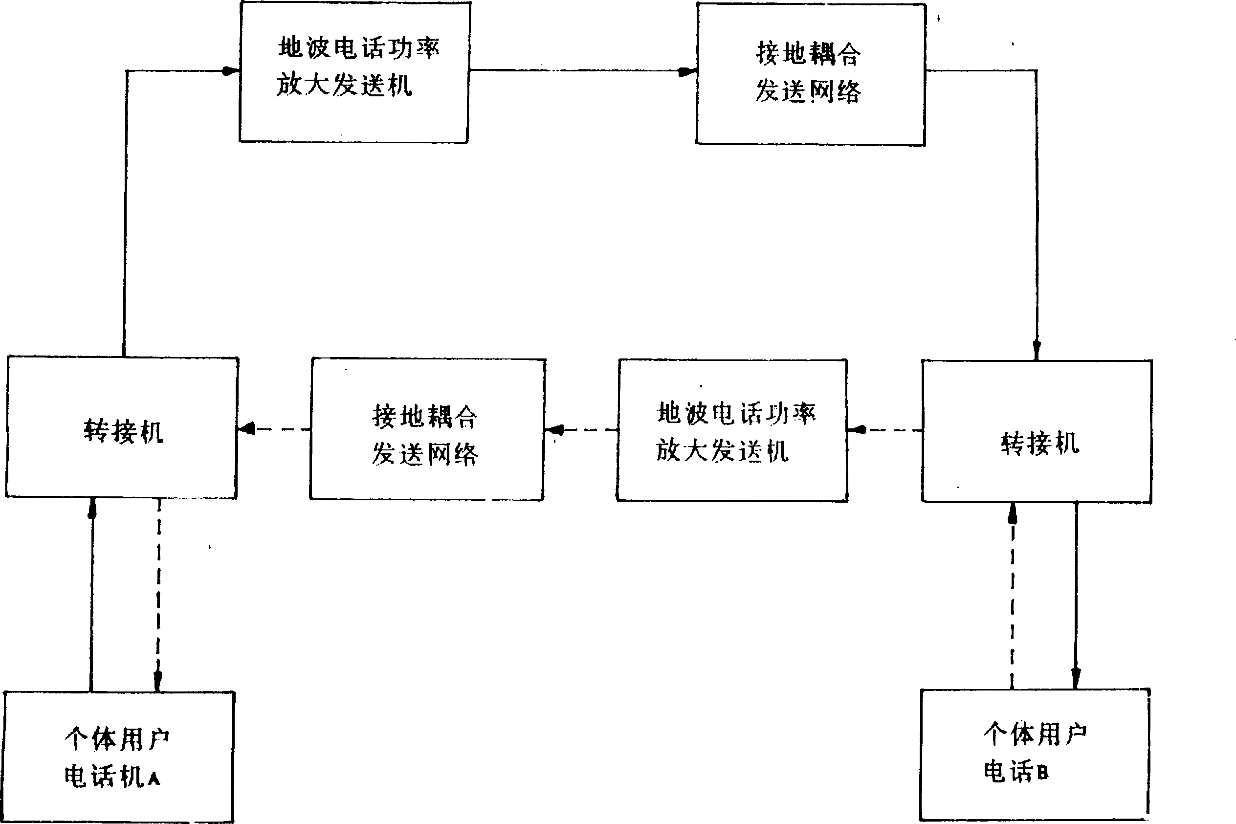
[0026] Example: see figure 1 , very low frequency ground wave telephone equipment, the (local) individual user telephone A picks up the phone to dial, and the signal is sent to the power amplifier transmitter of the ground wave telephone through the switchboard, and the high-power signal output by the power amplifier transmitter is fed back The wire is connected to the ground and coupled to the transmission network to radiate and propagate, and the signal is sent to the (other party) switching machine in the form of ground waves, and transferred to the other party's individual user phone B, and the signal from the party is demodulated by the receiving circuit and restored to voice , the other party's individual phone B picks up the hook, and returns the voice signal to the local party in the same way as above, and realizes a duplex intercom call between the individual user phones of both parties.
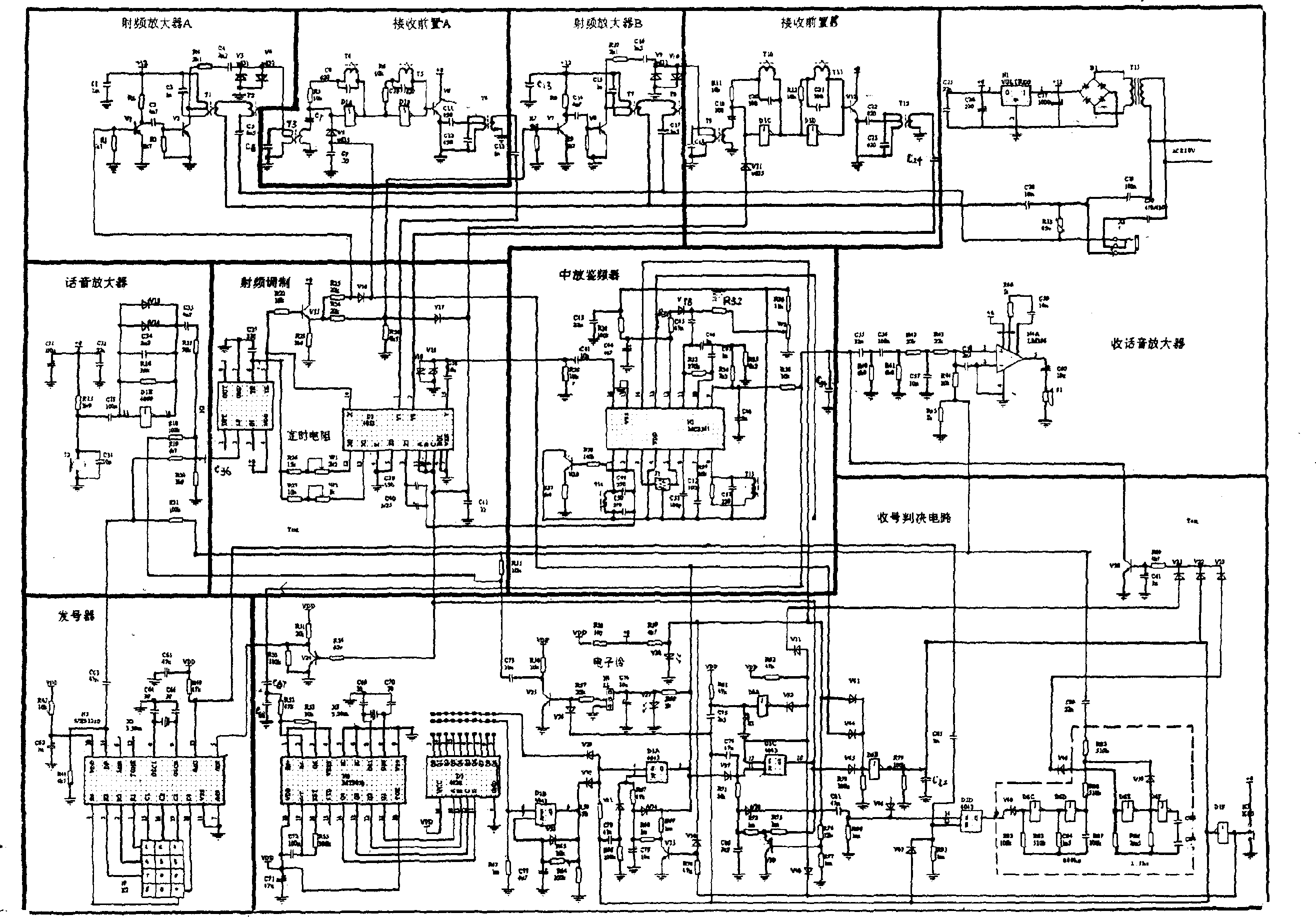
[0027] Individual user telephone circuit see figure 2Shown: The output of the...
PUM
 Abstract
Description
Claims
Application Information
 - Generate Ideas
- Intellectual Property
- Life Sciences
- Materials
- Tech Scout
- Unparalleled Data Quality
- Higher Quality Content
- 60% Fewer Hallucinations
Browse by: Latest US Patents, China's latest patents, Technical Efficacy Thesaurus, Application Domain, Technology Topic, Popular Technical Reports.
© 2025 PatSnap. All rights reserved.Legal|Privacy policy|Modern Slavery Act Transparency Statement|Sitemap|About US| Contact US: help@patsnap.com