Transmission and meshing clutch

A transmission and clutch technology, applied in the direction of clutches, clutches, mechanical drive clutches, etc. that mesh with each other, can solve the problems of shifting shock and abnormal noise, internal cycle torque increase, and inclination that cannot be reduced, so as to reduce the speed change Shock and abnormal noise, the effect of reducing shock and abnormal noise

Pending Publication Date: 2022-01-11
IKEYA FORMULA
View PDF7 Cites 0 Cited by
  • Summary
  • Abstract
  • Description
  • Claims
  • Application Information

AI Technical Summary

Problems solved by technology

[0011] However, since this guide surface is formed on the side of the rotation direction of the meshing teeth, the inclination cannot be reduced. For example, when the meshing teeth of a low-speed gear are disengaged, the internal circulation torque due to simultaneous meshing will increase significantly. big state
[0012] Therefore, when the meshing teeth are separated, due to the increased internal cyclic torque, the meshing surfaces of each other are pressed against each other, and they are relatively deviated in the direction of separation, and finally separated at the end of the engagement, and the internal cyclic torque is released. Due to this action , there is still a large shifting shock and abnormal noise

Method used


Image

  • Transmission and meshing clutch
  • Transmission and meshing clutch
  • Transmission and meshing clutch

Examples


Embodiment 1

[0079] [summary of transmission]

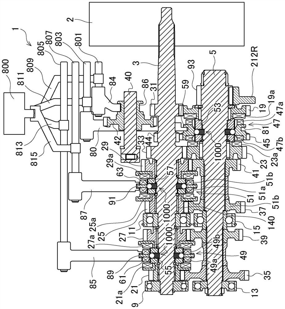
[0080] figure 1 It is a schematic sectional view showing a seamless shift transmission according to Embodiment 1 of the present invention.

[0081] Such as figure 1 As shown, the transmission 1 includes a solid main shaft 3 , a counter shaft 5 , and an idler shaft 40 as torque transmission members. These main shaft 3 and counter shaft 5 are rotatably supported by a transmission case (not shown) by bearings 9 , 11 , 13 , 15 and the like. The idler shaft 40 is fixed on the side of the transmission case.

[0082] In the above-mentioned main shaft 3 and countershaft 5, a first-speed gear 19, a second-speed gear 21, a third-speed gear 23, a fourth-speed gear 25, a fifth-speed gear 27, and a sixth-speed gear 29 are supported in appropriate positions as multi-stage gears. Gear change.

[0083] The first gear 19 and the third gear 23 on the above-mentioned auxiliary shaft 5 mesh with the output gears 31 and 33 of the main shaft 3, and the second...

Embodiment 2

[0222] Figure 20 , Figure 21 Example 2 is shown. Figure 20 It is a schematic configuration diagram of a system for canceling shifting. Figure 21 It is a flowchart for performing shift cancellation.

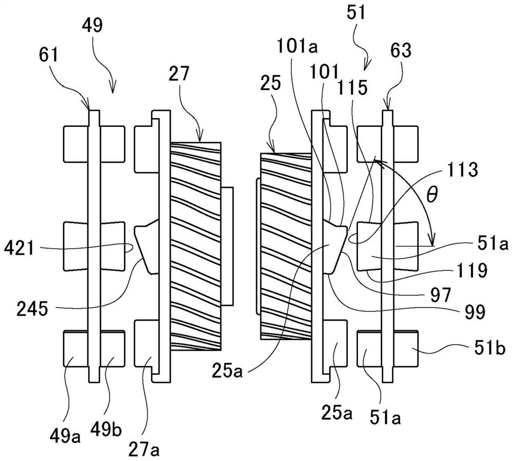
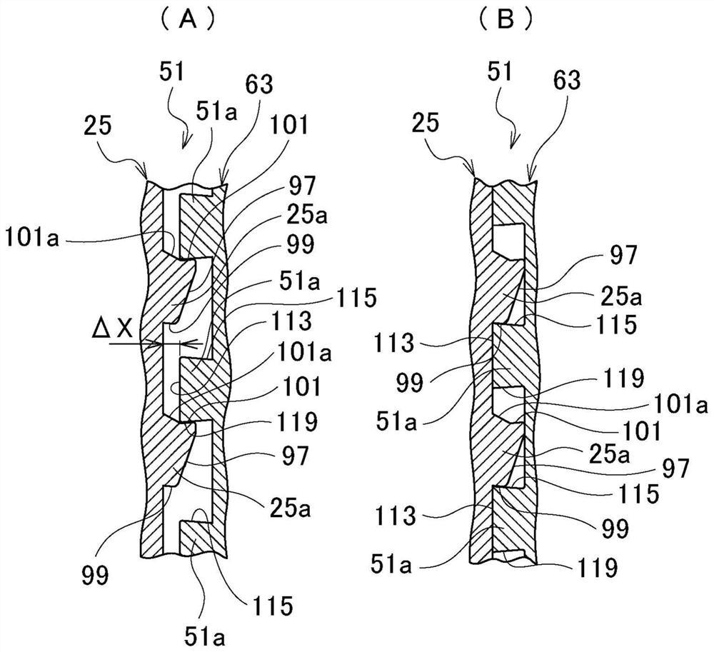
[0223] Figure 20 Indicates the action of the low-level meshing teeth when the high-level and low-level meshes at the same time. For example, the relationship between the clutch sleeve 63 and the fourth speed gear 25 is shown in the third meshing clutch 51 .


PUM


Abstract

The invention provides a transmission and a meshing clutch which can further reduce impact and abnormal sound when the meshing clutch is disengaged in a state where torque is applied. The transmission is characterized in that the transmission is provided with a meshing clutch (51) which is engaged with one gear stage by meshing and is disengaged when the engagement is changed to the other gear stage by simultaneous meshing, at the tooth crest of one or the other meshing teeth (51a, 25a), is provided with a disengagement guide part, and is provided with a movement mechanism that has the axial force for moving a rotating part (63) and releases the axial force by the generation of a sliding torque, is provided with a biasing mechanism (1000) that biases one of the rotating members (63) with a force smaller than the axial force generated by the movement mechanism so as to engage meshing teeth (51a, 25a), wherein a contact body of the biasing mechanism (1000) is disposed in a support hole formed in the torque transmission member (57) in the radial direction, and is provided with an abutment body that receives a radially urging force of the urging function section (1000) and a force conversion section that converts the direction of urging force into the axial direction and excites the axial movement of the one rotating member (63).

Description

technical field [0001] The present invention relates to a transmission and a meshing clutch for shifting speeds of automobiles, construction machines, agricultural vehicles, and the like. Background technique [0002] Generally, in a vehicle transmission using a single clutch, the driving force is interrupted when shifting, and shift shocks, acceleration delays, and the like are unavoidable. Also, in construction machines, agricultural machines, etc., which have high running resistance and low speed performance, if the driving force is interrupted during gear shifting, the gears may stop immediately and gear shifting is difficult. [0003] In contrast, known dual-clutch transmissions can suppress shift shock and acceleration delay without interruption of driving force. [0004] However, the dual-clutch transmission has problems of complicated structure and heavy weight. [0005] On the other hand, a seamless shift transmission using meshing teeth has attracted attention as...

Claims


Application Information

Patent Timeline
Patent Type & Authority Applications(China)
IPC IPC(8): F16H63/18F16H3/083F16D11/00
CPCF16H63/18F16H2061/0474F16H2063/3093F16H63/38F16H63/30F16D11/14F16H3/089F16H2003/0811F16H2003/0822F16H3/16F16H2200/0052F16H3/08F16H61/04
Inventor 池谷信二
Owner IKEYA FORMULA
Why Eureka
Try Eureka