Novel stem cutting machine device

A stem cutting machine, a new type of technology, applied in the treatment of tobacco, tobacco, application, etc., can solve the problems of unreasonable local structure of the stem cutting machine, damage to the bakelite ring gear, frequent failures, etc.

Pending Publication Date: 2019-08-06
HEILONGJIANG TOBACCO IND
View PDF8 Cites 0 Cited by
  • Summary
  • Abstract
  • Description
  • Claims
  • Application Information

AI Technical Summary

Problems solved by technology

[0002] The model SQ218D stem cutter currently used in the cigarette workshop, in order to meet the production capacity demand of 3000 kg of stem wire in the silk workshop of the factory, during use, due to t

Method used


Image

  • Novel stem cutting machine device
  • Novel stem cutting machine device
  • Novel stem cutting machine device

Examples


Embodiment 1

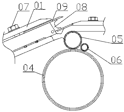
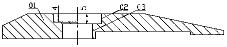
[0022] A new type of stem cutter device, including a pressure knife plate 01, a bakelite ring gear 04, a planetary wheel 05, a driving wheel 06, a compression screw 07, and a knife edge seat 08. The pressure knife plate 01 has a No. 1 installation hole 02 inside, The bottom of No. 1 installation hole 02 has No. 2 installation hole 03. The cantilever length of pressure knife plate 01 is 86.5mm. The left side of 02, the right side of the pressure plate 01 is connected to the blade 09, the bottom of the blade 09 is connected to the knife edge seat 08, the right side of the knife edge seat 08 is connected to the planetary wheel 05, the lower part of the planetary wheel 05 is connected to the bakelite ring gear 04, and the bakelite tooth The ring 04 meshes with the planetary gear 05, the right side of the bakelite ring gear 04 is connected to the driving wheel 06, the bakelite ring gear 04 is meshed with the driving wheel 06, and the pressure angle between the bakelite ring gear 04 ...

Embodiment 2

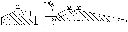
[0029] The No. 1 installation hole 02 is an inclined hole, the bottom surface of the No. 1 installation hole 02 is higher on the left side and the right side is lower. The angle between the center line of the No. 1 installation hole 02 and the top surface of the pressure knife plate 01 is 89° to ensure the installation of the compression screw After 07, the compression screw 07 is in contact with the left end of No. 1 installation hole 02, and the right end is suspended, so that there is a certain gap between the pressure plate 01 and the knife edge seat 08, the cantilever of the pressure plate 01 is changed from 119mm to 86.5mm, and the pressure plate 01 is deformed The amount is reduced from 0.7586mm to 0.285mm, reducing the pressure of the knife-edge seat 08 on the planetary gear 05, thereby reducing the meshing force between the planetary gear 05 and the bakelite ring gear 04, reducing the wear of the bakelite ring gear 04, and reducing the pressure of the bakelite ring gear...

Embodiment 3

[0031] Bakelite gear 04 has a width of 16mm, the modulus of bakelite gear 04 is 3mm, the number of teeth of bakelite gear 04 is 154, and the number of teeth of drive wheel 06 is 17. Keep the width of bakelite gear 04 unchanged and change the module of related bakelite gear 04 The increase from 2mm to 3mm increases the strength of the bakelite ring gear 04, thereby reducing the wear and tear of the bakelite ring gear 04, reducing the damage rate of the bakelite ring gear 04, and making the overall structure more reasonable.


PUM

PropertyMeasurementUnit
Widthaaaaaaaaaa
Widthaaaaaaaaaa
Modulusaaaaaaaaaa

Abstract

The invention provides a novel stem cutting machine device. The device comprises a cutter pressing plate, a bakelite gear ring, a planet wheel, a driving wheel, a compression screw and a cutter edge base. A first installation hole is formed in the cutter pressing plate. A second installation hole is formed in the bottom of the first installation hole. The length of the cantilever of the cutter pressing plate is 86.5 mm. The cutter pressing plate is connected with the cutter edge base through the compression screw. The left side of the compression screw is connected with the left side of the first installation hole. A blade is connected to the right side of the cutter pressing plate. The cutter edge base is connected to the bottom of the blade. The planet wheel is connected to the right side of the cutter edge base. The bakelite gear ring is connected to the lower portion of the planet wheel and is meshed with the planet wheel. A driving wheel is connected to the right side of the bakelite gear ring, and the bakelite gear ring is meshed with the driving wheel. The pressure angle between the bakelite gear ring and the driving wheel is 20 degrees.

Description

technical field [0001] The invention relates to the field of stem cutters, in particular to a novel stem cutter device. Background technique [0002] The model SQ218D stem cutter currently used in the cigarette workshop, in order to meet the production capacity demand of 3000 kg of stem wire in the silk workshop of the factory, during use, due to the unreasonable local structure of the stem cutter, the knife in the SQ218D stem cutter The bakelite ring gear damage problem related to the mouth seat is particularly prominent, and failures are frequent. Contents of the invention [0003] The present invention aims at the above-mentioned deficiencies existing in the prior art, and provides a novel stem cutter device with reasonable structure. [0004] The purpose of the present invention is to realize through the following technical solutions: [0005] A new type of stem cutter device, including a pressure knife plate, a Bakelite ring gear, a planetary wheel, a driving wheel,...

Claims


Application Information

Patent Timeline
IPC IPC(8): A24B5/04
CPCA24B5/04
Inventor 孙利国安毅石中金王廷刘相君陆国强梁伟王阁明李大为黄辛明魏紫薇周碧波王晓丹刘伟华杨宪芬李建宇江楠吴凤娇关体青聂红资刘翠芬陈书军
Owner HEILONGJIANG TOBACCO IND
Why Eureka
Try Eureka