Motion execution mechanism based on motion amplification principle and robot
A motion amplification and actuator technology, applied in the field of mechanics, can solve the problems of complex structure of multi-degree-of-freedom motion mechanisms, and achieve the effects of easy processing, reducing assembly errors, and reducing processing difficulty and cost.
- Summary
- Abstract
- Description
- Claims
- Application Information
AI Technical Summary
Problems solved by technology
Method used
Image

Examples
Embodiment 1
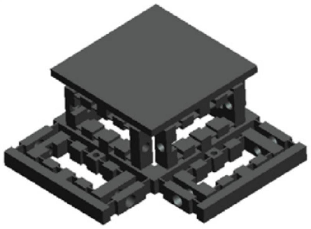
[0030] The present invention provides a motion actuator based on the principle of motion amplification, which includes a plurality of parallel branch chains 1, and each branch chain 1 includes:
[0031] Bridge-type amplification mechanism for translational movement;
[0032] The lever magnifying mechanism is used to realize the rotary motion, and the lever magnifying mechanism is connected in series with the bridge type magnifying mechanism.
[0033] Multiple branch chains 1 connected in parallel shorten the kinematic chain, reduce assembly errors, and improve precision; and each branch chain 1 includes a bridge-type amplification mechanism and a lever amplification mechanism connected in series, which realizes multi-degree-of-freedom movement while simultaneously The structure is simplified, and the processing difficulty and cost are reduced.
[0034] Specifically, the number of branch chains 1 is three, and the three branch chains 1 are associated with each other at an angl...
Embodiment 2
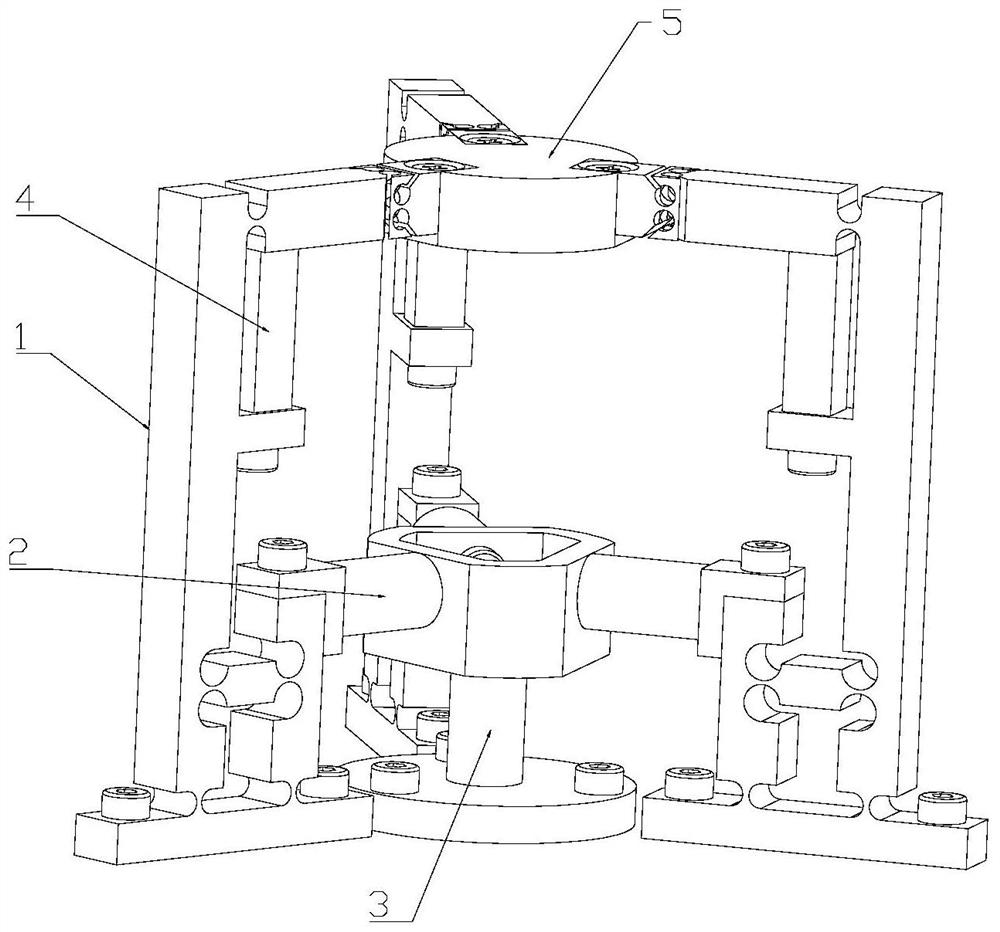
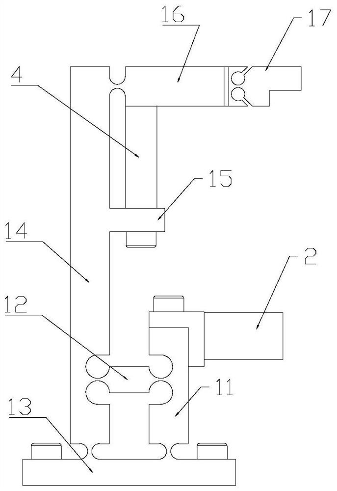
[0045] Such as figure 2 As shown, the present invention provides a 2R3T motion actuator based on the principle of motion amplification.
[0046]The 2R3T motion actuator includes a branch chain 1, a voice coil motor 2, a voice coil motor fixing bracket 3, piezoelectric ceramics 4 and an operating platform. Among them, the voice coil motor 2 is fixed on the voice coil motor fixing bracket 3 by M2 screws at an angle of 120° between each other; the bottom of the single branch chain 1 is connected with the voice coil motor 2 to form a bridge-type amplification mechanism, and the surface of the control mechanism Internal movement; a piezoelectric ceramic 4 is arranged above to form a lever amplification mechanism to control the out-of-plane movement of the mechanism; three branch chains 1 are connected in parallel at an angle of 120° between each other, and are fixed on the operating platform by M2 screws; a single branch chain 1 The bottom is fixed with the bottom of the voice co...
PUM
 Abstract
Description
Claims
Application Information
PatSnap Eureka turns technology decisions into work you can execute. Powered by our Innovation Knowledge Graph, it runs expert workflows across engineering, life sciences, materials and intellectual property. Get your review-ready output in minutes.


