Full-rolling movable tooth one-tooth-difference planetary speed reducer

A planetary reducer, movable tooth technology, applied in mechanical equipment, gear transmission, belt/chain/gear, etc., can solve the problems of not eliminating large sliding friction, unsuitable for high-power transmission, and complex structure of the movable gear frame. , to achieve the effect of simple structure, long life and easy processing

Pending Publication Date: 2020-03-31
XIAN UNIV OF SCI & TECH
View PDF0 Cites 0 Cited by
  • Summary
  • Abstract
  • Description
  • Claims
  • Application Information

AI Technical Summary

Problems solved by technology

Although there are rolling (double row) gear holders and rolling bearings (called "full rolling") in the movable teeth, the radial guide groove movable gear rack is still used, which does not eliminate the large friction of sliding, but makes the structure Very complicated
[0003] The input and output ends of the planetary reducer with movable teeth and less tooth difference generally adopt radial guide groove transmission mechanism, which has a complex structure and low transmission efficiency, generally 80% to 85%, which is not suitable for high-power transmission. Hole pins or There are many guide grooves, generally 20 to 80 guide grooves, and 8 to 16 pairs of hole pins, which makes the processing precision of the entire input and output mechanism very high
The movable rack (seat) has a complex structure, especially the radial guide groove movable rack has weak strength
[0004] In short, the movable tooth planetary transmission reducer described above is only suitable for small power transmission.

Method used


Image

  • Full-rolling movable tooth one-tooth-difference planetary speed reducer
  • Full-rolling movable tooth one-tooth-difference planetary speed reducer
  • Full-rolling movable tooth one-tooth-difference planetary speed reducer

Examples


Embodiment Construction

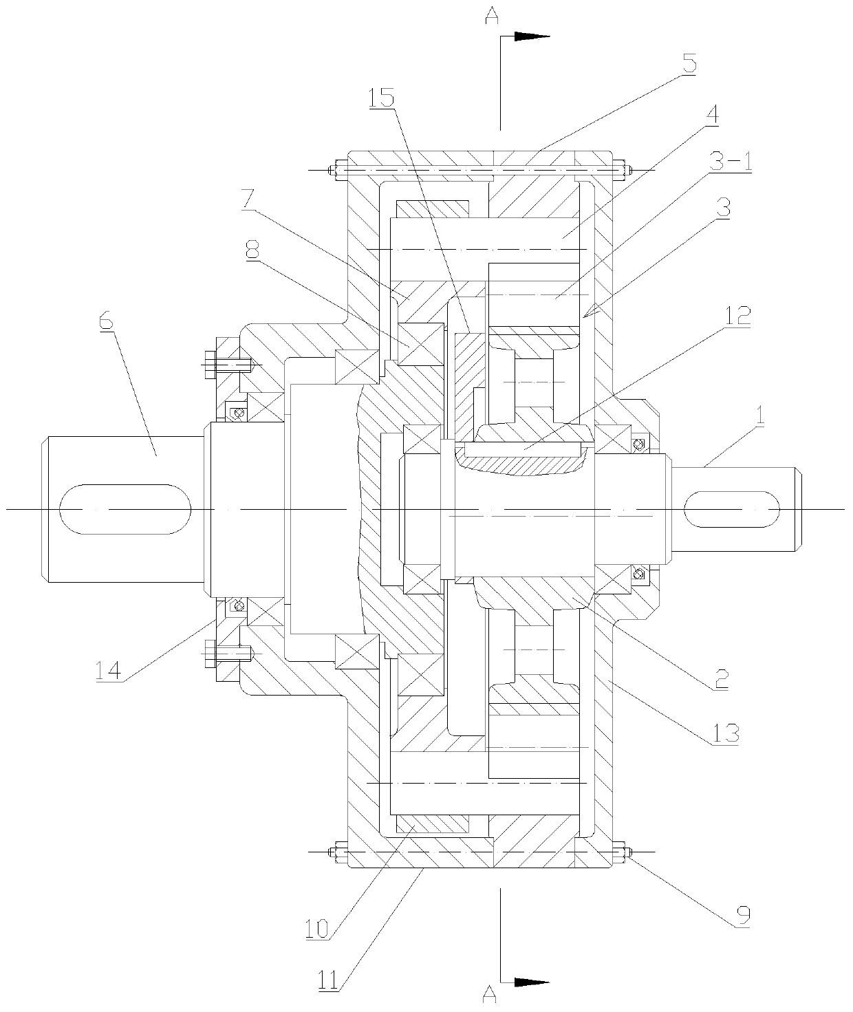
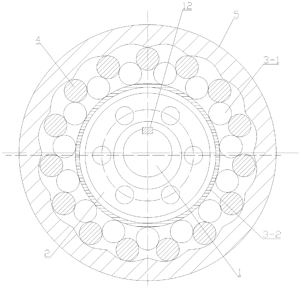
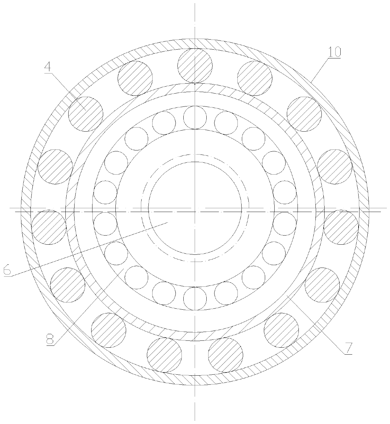
[0033] Such as figure 1 , figure 2 with image 3 As shown, the present invention includes a rolling-type input mechanism and an eccentric ring-type output mechanism, between which the input mechanism and the eccentric ring-type output mechanism perform reduction transmission in a rolling manner through a tooth difference planetary transmission mechanism, and the input mechanism includes The input shaft 1 and the eccentric sleeve 2 sleeved on the input shaft 1, the one-tooth difference planetary transmission mechanism includes the inner ring gear 5 and the movable ring gear arranged in the inner ring gear 5, and the movable ring gear includes a plurality of The movable tooth 4 meshed with the tooth profile of the inner ring gear 5, and the arm bearing 3 without outer ring which can play the role of the tooth seat ring is arranged between the input end of the movable ring gear and the outer ring of the eccentric sleeve 2, The input end of the movable tooth 4 in the movable ri...


PUM


Abstract

The invention discloses a full-rolling movable tooth one-tooth-difference planetary speed reducer. The speed reducer comprises a rolling type input mechanism and an eccentric ring type output mechanism, wherein the input mechanism and the eccentric ring type output mechanism are in speed reduction transmission through a tooth difference planetary transmission mechanism. The speed reducer is advantaged in that a rotating arm bearing and a gear seat ring are combined into a whole, an input shaft drives an eccentric sleeve to eccentrically rotate and pushes a tumbler bearing without an outer ring, oscillating teeth are meshed with an inner arc tooth profile of an inner gear ring to cooperate for planetary motion, a concentric bearing between the eccentric ring and an output shaft has functions of decomposition, balance and deviation compensation of planetary motion and conversion of eccentric motion into fixed-axis rotation, an outer ring of the concentric bearing bears high-speed revolution, an inner ring of the concentric bearing bears low-speed rotation and resultant force with the same eccentric distance, so the output shaft generates low-speed and large-torque speed reduction transmission and rolling to replace sliding, transmission efficiency is higher, no guide groove or pin hole is formed on an eccentric ring entity, the strength of the whole structure is fully guaranteed,and the structure adapts to the high-efficiency and high-power speed reducer.

Description

technical field [0001] The invention belongs to the technical field of a planetary reducer with a small tooth difference, and in particular relates to a planetary reducer with a fully rounded movable tooth and a tooth difference. Background technique [0002] At present, movable tooth transmissions are generally divided into roller movable tooth transmissions, movable tooth pinwheel transmissions and T-shaped movable tooth transmissions. The basic feature of this kind of movable tooth transmission is that the movable tooth at the input end and the output roller are combined into one, and they are all placed in a radial guide groove mechanism of a movable tooth frame. Its structure is simple, but the input mechanism has a tooth difference. The movable tooth movement of the transmission and output mechanism is a crank-slider mechanism, which becomes very complicated, generates sliding friction, wears and generates serious heat, and can only be applied to low-power transmission...

Claims


Application Information

Patent Timeline
Patent Type & Authority Applications(China)
IPC IPC(8): F16H1/34
CPCF16H1/34
Inventor 毛开友张红兵
Owner XIAN UNIV OF SCI & TECH
Why Eureka
Try Eureka