Conveying equipment for batching system

A technology of conveying equipment and batching system, which is applied to conveyors, conveyor objects, transportation and packaging, etc., can solve the problems of raising large dust, easy deviation of tapes, and difficulty in use, and achieves enhanced lateral rigidity and enhanced cleaning strength. , The effect of convenient replacement and maintenance

A technology of conveying equipment and batching system, which is applied to conveyors, conveyor objects, transportation and packaging, etc., can solve the problems of raising large dust, easy deviation of tapes, and difficulty in use, and achieves enhanced lateral rigidity and enhanced cleaning strength. , The effect of convenient replacement and maintenance

CN113928801AActive Publication Date: 2022-01-14HUBEI TIANYI MACHINERY CO LTD

Image

  • Conveying equipment for batching system
  • Conveying equipment for batching system
  • Conveying equipment for batching system

Examples


Embodiment Construction

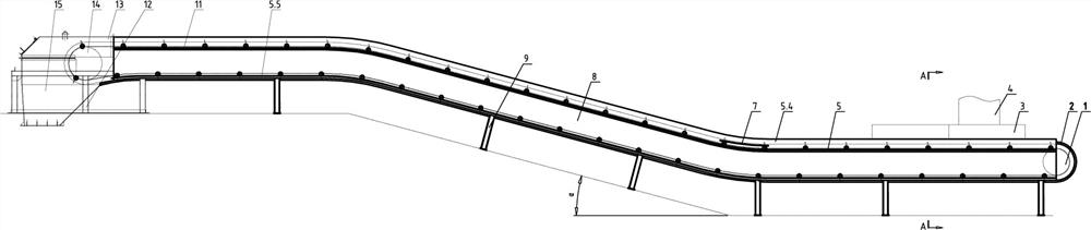
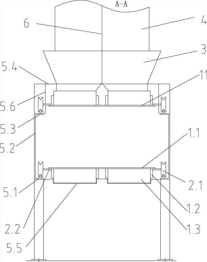
[0045] like Figure 1-2 As shown, a batching system conveying equipment includes a reversing drum 1, an arc-shaped machine trough 2, a material guide trough 3, a feed chute 4, a track 5, a partition 6, a pressing rail 7, a frame 8, and legs 9. Material 10, multi-channel conveying tape 11, head frame 12, head shield 13, drive roller 14, head funnel 15.

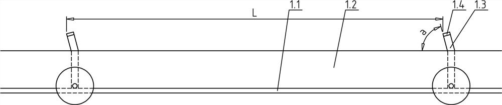
[0046] Specifically, such as Figure 3-4As shown, the multi-channel conveyor belt 11 includes a base belt 1.1, and a plurality of skirts 1.2 are vulcanized on the base belt 1.1. When the equipment batches and conveys two different materials at the same time, there are four skirt ribs 1.2, and each two groups of skirt ribs 1.2 form a set of conveying channels, and the distance between the two sets of conveying channels is B, separated from each other. A transverse partition 1.3 is arranged at every distance L in each group of conveying channels. The distance L is designed according to the conveying volume and equipment layout...


PUM


Abstract

Conveying equipment for a batching system comprises a machine frame, a turnabout drum and a transmission drum are installed on the machine frame, and a multi-channel conveying rubber belt is wound between the turnabout drum and the transmission drum; the machine frame comprises main plate faces, and the main plate faces, lower plate faces and upper plate faces are welded to form the integrated machine frame and form rails; the left and right sides of the lower plate faces are connected with return receiving grooves, and the upper plate faces are connected with an upper sealing shell; the multi-channel conveying rubber belt comprises a base belt, a plurality of pairs of skirt flanges are longitudinally arranged on the base belt at intervals, transverse partition plates are arranged on the portion, between each pair of skirt flanges, of the base belt in the length direction at intervals, and walking wheels are arranged on the left side and the right side of the base belt and slide along the rails; and when the transverse partition plates run to a return section, materials in the return receiving grooves are cleaned. According to the conveying equipment for the batching system, different materials can be conveyed simultaneously, deviation of the rubber belt is avoided, and the materials at the return section can be automatically cleaned and returned.

Description

technical field [0001] The invention relates to a conveyor, in particular to a batching system conveying equipment. Background technique [0002] Belt conveyor, also known as belt conveyor, is mainly composed of intermediate frame, conveyor belt, idler roller, roller, tensioning device, transmission device and so on. The main operating principle is that the closed conveyor belt is tightly sleeved on the two end rollers, and the roller that drives the conveyor belt to rotate is called the driving roller (drive roller); the other roller that only changes the moving direction of the conveyor belt is called the redirecting roller. The drive pulley is driven by a motor through a reducer, and the conveyor belt is dragged by the friction between the drive pulley and the conveyor belt. The drive pulleys are generally installed on the discharge end in order to increase traction and be easy to drag. The material is fed on the feed-side near the tail and landed on the rotating convey...

Claims


Application Information

Patent Timeline
14 Jan 2022
Publication
CN113928801A
IPC
B65G23/04; B65G15/60; B65G21/20; B65G41/00; B65G47/74; B65G15/56; B65G47/18
CPC
B65G23/04; B65G15/60; B65G21/20; B65G41/006; B65G47/74; B65G15/56; B65G47/18; Y02P70/10
Inventors
ι»„δΏŠζ°; δΈ‡εŽšε…΅