Laser cladding device and method for repairing surface of pump shell

A technology of laser cladding and surface repair, applied in metal material coating process, coating and other directions, can solve the problems of reduced efficiency, no adjustment effect, inconvenient laser head adjustment operation, etc., to achieve easy operation, stable fixation, and difficult shedding effect

Pending Publication Date: 2022-01-14
客镭定科技南通有限公司
View PDF8 Cites 0 Cited by
  • Summary
  • Abstract
  • Description
  • Claims
  • Application Information

AI Technical Summary

Problems solved by technology

[0003] However, most of the existing laser cladding does not have a good adjustment effect, and it is not convenient to adjust the laser head. At the same time, the powder coating on the surface of the pump casing and the laser cladding operation need to be carried out separately, which reduces the work efficiency. Therefore, A laser cladding device and cladding method for pump casing surface repair are designed here to solve the above problems

Method used


Image

  • Laser cladding device and method for repairing surface of pump shell
  • Laser cladding device and method for repairing surface of pump shell
  • Laser cladding device and method for repairing surface of pump shell

Examples


Embodiment 1

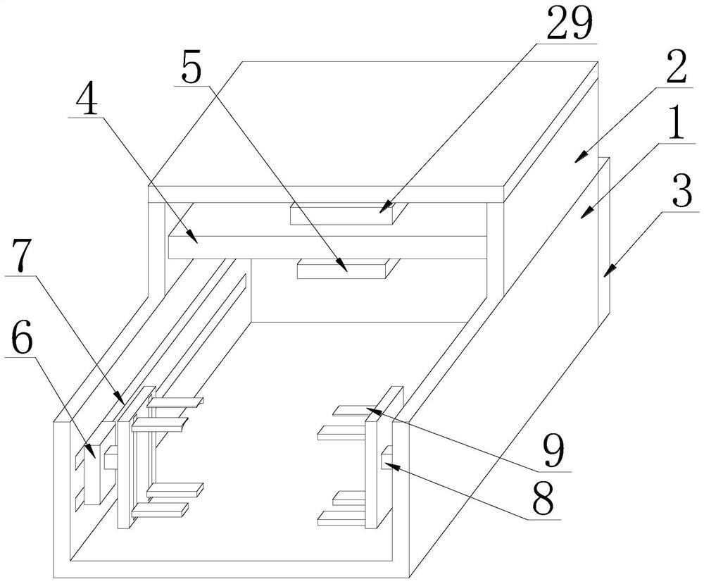
[0026] See Figure 1-5 The present embodiment provides a laser cladding apparatus and a moltenling method for the surface of the pump shell, including the transport shell 1, and fixedly connected to the end surface of the conveying shell 1, and the inside of the fixing plate 3 is provided with a rotating mechanism. 26. The internal symmetry of the conveying shell 1 is provided with two limit plate 7, and the inside of the two limit plate 7 is provided with a fixing mechanism 27. The top end of the conveying shell 1 is fixedly connected to the treatment case 2, and the internal fixation of the processing case 2 is fixed. The top portion of the support plate 4 is connected to the top of the support plate 4, and a movable plate 5 is provided at the bottom of the support plate 4, and the bottom portion of the movable plate 5 is connected to the laser head 22.

[0027] The existing laser deserted, mostly does not have a good adjustment effect, inconvenient to adjust the laser head, whil...

Embodiment 2

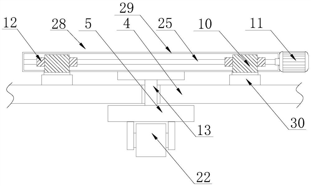
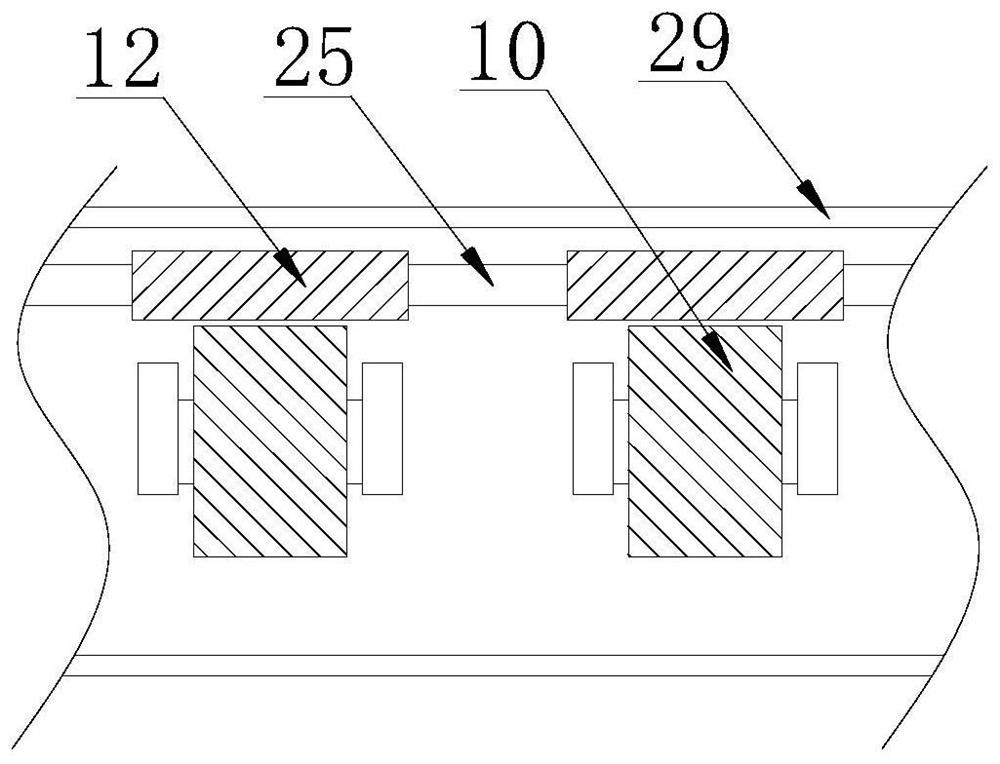
[0036] See image 3 Or 4, further improvements on the basis of Example 1:

[0037] In order to make the moving member 6 more stable in movement, there is a phenomenon of shake, and there is a limit bit rod 15 between the two first threaded rods 14, the limit rod 15 and the two first threaded rods 14 welded, the limit rod 15 The moving block 17 is provided, and the moving block 17 is slidably connected to the limit lever 15, the moving block 17 and the two slider 16 are welded.

[0038] In this embodiment, by increasing the limit rod 15 in the conveying shell 1, it is possible to cause the slider 16 on the first threaded rod 14 to move, in turn, the moving block 17 on the limit lever 15 can be moved, thereby It can act as a limit, thereby increasing the stability of the moving parts 6 during movement, so that the phenomenon of shaking sound occurs when the moving pump shell is moved.

[0039] In order to make the laser cladding of the pump shell, the processing is more complete, onl...


PUM


Abstract

The invention discloses a laser cladding device and method for repairing the surface of a pump shell, and relates to the technical field of laser cladding. The laser cladding device comprises a conveying shell. A fixing plate is fixedly connected to one end face of the conveying shell, and a rotating mechanism is arranged inside the fixing plate. According to the laser cladding device and method, the purpose of limiting and clamping the pump shell can be achieved through a fixing mechanism, fixing can be stable, the falling phenomenon is not prone to occurring, and the operation is easy and convenient; and the rotating mechanism can achieve the effect that rotation of first threaded rods is adjusted to drive sliding blocks to move so as to achieve movement of the pump shell, the pump shell can be moved to the bottom of a laser head, a moving mechanism can have an effect of adjusting the movement of the laser head, then the position of the laser head can be adjusted according to different working requirements, the moving mechanism cooperates with a rotating device in a moving part, and therefore the purpose that the pump shell fixed by two clamping plates is adjusted to achieve a rotating effect can be achieved, and the laser cladding quality is improved.

Description

Technical field [0001] The present invention relates to the field of laser cladding techniques, in particular a laser cladding apparatus for repairing the surface of the pump shell and a moltenling method. Background technique [0002] During the use of the pump shell, it is prone to the phenomenon of damage to the surface of the pump shell. At this time, by laser cladding, it can be repaired on the surface of the pump shell. [0003] However, the existing laser is cleaved, most of which does not have a good adjustment effect, not convenient to adjust the laser head, while the pump shell surface is applied to the surface of the laser needed to be separated, thereby reducing the efficiency of the operation, so A laser cladding apparatus and a moltenling method for a pump shell surface are designed here to facilitate solving the above problems. Inventive content [0004] It is an object of the present invention to provide a laser cladding apparatus and a molten method for a pump s...

Claims


Application Information

Patent Timeline
Patent Type & Authority Applications(China)
IPC IPC(8): C23C24/10
CPCC23C24/10
Inventor 蔡淳佑
Owner 客镭定科技南通有限公司
Why Eureka
Try Eureka