Pre-stressed foundation with replaceable anchor bolts

A prestressed and anchored technology, applied in infrastructure engineering, construction, sheet pile walls, etc., can solve problems such as difficulty, time-consuming, labor-intensive cost, and inability to realize the reuse of concrete foundations, so as to save maintenance costs and avoid risks. , the effect of eliminating hidden risks

Pending Publication Date: 2022-01-14
湖北华飞新能源科技有限公司
View PDF0 Cites 0 Cited by
  • Summary
  • Abstract
  • Description
  • Claims
  • Application Information

AI Technical Summary

Problems solved by technology

[0004] However, since the prestressed anchor bolts are pre-buried in the concrete foundation, it is difficult to implement on-site repairs. It is necessary to destroy the concrete around the prestressed anchor bolts, and it is also a problem that the anchor bolts are separated from the upper and lower anchor plates. This method is time-consuming, laborious and costly. , the concrete foundation cannot be reused, so a low-cost and easy-to-dismantle broken anchor technology is needed

Method used


Image

  • Pre-stressed foundation with replaceable anchor bolts
  • Pre-stressed foundation with replaceable anchor bolts
  • Pre-stressed foundation with replaceable anchor bolts

Examples


Embodiment 1

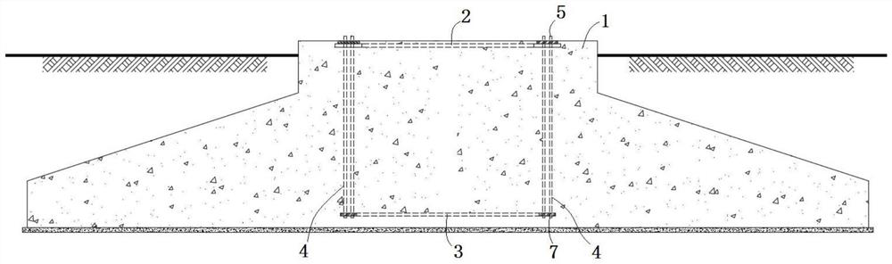
[0032] like figure 1 As shown, a prestressed foundation with replaceable anchor bolts includes a concrete foundation 1 formed by pouring reinforced concrete, and a prestressed anchor bolt 4 assembly embedded in the concrete foundation 1 . The concrete foundation 1 can be a hollow structure, and a manhole can be arranged on the top of the hollow structure for workers to enter into the concrete foundation 1 to perform relevant maintenance work. In this embodiment, the prestressed anchor bolt 4 assembly has a ring structure, and the inner and outer steel formworks are respectively provided on the inner and outer sides of the prestressed anchor bolt 4 assembly to increase the stability of the concrete around the prestressed anchor bolt 4 assembly.

[0033] The prestressed anchor bolt 4 assembly includes an upper anchor plate 2 embedded in the top of the concrete foundation 1, a lower anchor plate 3 embedded in the concrete bottom, and several prestressed anchor bolts 4. The upper ...

Embodiment 2

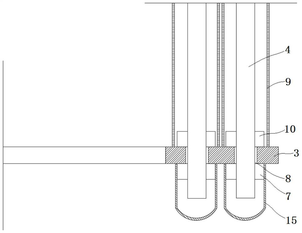
[0038] like image 3As shown, the bottom of the prestressed anchor bolt 4 is provided with a third nut 10 on the upper part of the lower anchor plate 3 . When the anchor bolt breaks, the prestressed anchor bolt 4 broken at the lower part will detach from the lower anchor plate 3 downward due to the reaction force, so that the connection between the prestressed anchor bolt 4 and the lower anchor plate 3 will fail, and the adjacent prestressed anchor bolt at the fracture will be seriously damaged. The support of the bolt 4 is balanced, and the thread of the second nut 7 is easily damaged, and the prestressed anchor bolt 4 cannot be connected again due to thread deformation. A third nut 10 is arranged on the top of the lower anchor plate 3, so that the bottom of the prestressed anchor bolt 4 is fixedly connected to the lower anchor plate 3. When the anchor bolt breaks, the prestressed anchor bolt 4 is locked by the second nut 7 and the third nut 10. On the lower anchor plate 3, ...

Embodiment 3

[0042] like Figure 5 As shown, the inner side or the outer side of the first locking structure 14 is provided with a dismounting thread 16, the direction of rotation of the dismounting thread 16 is opposite to that of the external thread 13, and the thread radius of the dismounting thread 16 is greater than the thread radius of the internal thread 12 .

[0043] The first through hole 6 of the upper anchor plate 2 is provided with a shrinkage cavity structure 17, and the upper part of the shrinkage cavity structure 17 is provided with a second locking structure 18 wider than the aperture of the first through hole 6. The shrinkage cavity The lower part of the structure 17 is inserted into the first through hole 6, and the shrinkage cavity structure 17 is provided with a third through hole 19 through which the prestressed anchor bolt 4 passes. In specific use, the shrinkage cavity structure 17 is installed on the upper anchor plate 2, the shrinkage cavity structure 17 is insert...


PUM


Abstract

The embodiment of the invention discloses a pre-stressed foundation with replaceable anchor bolts. The pre-stressed foundation comprises a concrete foundation and a pre-stressed anchor bolt assembly pre-buried in the concrete foundation, the pre-stressed anchor bolt assembly comprises an upper anchor plate pre-buried at the top of the concrete foundation, a lower anchor plate which is pre-buried at the bottom of concrete and the plurality of pre-stressed anchor bolts, the upper ends of the pre-stressed anchor bolts vertically penetrate through first through holes of the upper anchor plate and are connected with first nuts, the lower ends of the pre-stressed anchor bolts vertically penetrate through second through holes of the lower anchor plate and are connected with second nuts, outer sleeves are arranged on portions, between the upper anchor plate and the lower anchor plate, of the pre-stressed anchor bolts, the upper ends and the lower ends of the outer sleeves are connected with the upper anchor plate and the lower anchor plate respectively in a sealed mode, and sealing sleeves are arranged at the bottoms of the pre-stressed anchor bolts. According to the pre-stressed foundation, the outer sleeves are arranged in the middle of the anchor bolts, the sealing sleeves are arranged at the bottom of the anchor bolts, the pre-stressed anchor bolts are completely isolated from the concrete foundation, the pre-stressed anchor bolts are detached, the purpose that the anchor bolts are replaceable and recyclable is achieved, replacement construction is easy and convenient, and a large amount of maintenance cost is saved.

Description

technical field [0001] The embodiment of the present invention relates to the technical field of wind turbine foundations, in particular to a prestressed foundation with replaceable anchor bolts. Background technique [0002] With the continuous maturity of wind power technology and the substantial increase of single unit capacity, the safe operation of wind turbines puts forward higher requirements on the reliability of tower foundations. At present, anchor bolt foundations composed of prestressed anchor bolt components and concrete foundations are widely used. On various types of wind turbines in inland wind farms. [0003] Among them, the prestressed anchor bolt assembly is composed of several anchor bolts and an anchor cage ring composed of upper and lower anchor plates. The anchor bolt foundation is formed by one-time pouring. After being fixed by the upper and lower anchor plates, it is connected with the flange of the lower section of the tower. During the operation ...

Claims


Application Information

Patent Timeline
Patent Type & Authority Applications(China)
IPC IPC(8): E02D27/42E02D27/44E02D5/74
CPCE02D27/425E02D27/44E02D5/74E02D2600/30
Inventor 马云龙
Owner 湖北华飞新能源科技有限公司
Why Eureka
Try Eureka