
Connecting joint structure for steel structure beam column

A technology of beam-column connection and steel structure, which is applied in the direction of building construction and construction, can solve the problems that the overall stability of beams and columns cannot be guaranteed, and the stability of steel columns is poor, so as to improve the connection stability, facilitate positioning, and improve The effect of connection strength

Active Publication Date: 2022-01-14
THE SIXTH CONSTR CO LTD OF CHINA NAT CHEM ENG
View PDF14 Cites 2 Cited by
  • Summary
  • Abstract
  • Description
  • Claims
  • Application Information

AI Technical Summary

Problems solved by technology

When the box girder is connected to the column, rigid connection is usually used, and the diaphragm corresponding to the beam flange runs through the box column. Since the cross section of the steel beam connected to the column is not exactly the same, some diaphragms are very close to each other, and the steel column is covered by the transverse diaphragm. The partition is divided into a small section, and there are many welds in the joint area of ​​the steel column, and the stress concentration is obvious, resulting in poor stress stability of the steel column, and the overall stability of the beam-column connection cannot be guaranteed

Method used


Image

  • Connecting joint structure for steel structure beam column
  • Connecting joint structure for steel structure beam column
  • Connecting joint structure for steel structure beam column

Examples


Embodiment Construction

[0026] The present invention will be further described in detail below in conjunction with the accompanying drawings, so that those skilled in the art can implement it with reference to the description.

[0027] It should be noted that the experimental methods described in the following embodiments, unless otherwise specified, are conventional methods, and the reagents and materials, if not otherwise specified, can be obtained from commercial sources; in the description of the present invention, The terms "landscape", "portrait", "top", "bottom", "front", "rear", "left", "right", "vertical", "horizontal", "top", "bottom", The orientation or positional relationship indicated by "inner", "outer", etc. is based on the orientation or positional relationship shown in the drawings, which is only for the convenience of describing the present invention and simplifying the description, and does not indicate or imply that the referred device or element must have Certain orientations, co...


PUM


Abstract

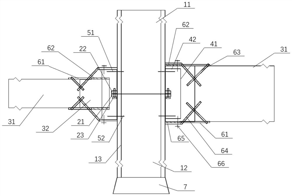
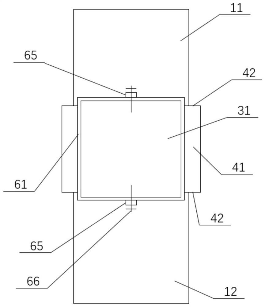
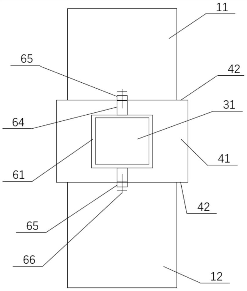
The invention discloses a connecting joint structure for a steel structure beam column. The structure comprises a steel structure column which comprises a plurality of layers of column bodies, wherein every two adjacent layers of column bodies are connected through a connection device; a steel structure beam which comprises a box girder; flange partition plates which are arranged at the end, connected with the steel structure column, of the box girder, wherein the flange partition plates comprise a plurality of partition plates which are continuously arranged in the circumferential direction of the section of the end of the box girder, and any partition plate extends outwards along the edge of the box girder; and a joint connecting mechanism which is arranged outside the connecting device in a sleeving mode in the circumferential direction of the steel structure column, wherein the joint connecting mechanism is connected with the steel structure column and the steel structure beam, and forms a closed space jointly formed with the joint connecting mechanism, the flange partition plates and the outer side wall of the steel structure column. The joint connecting mechanism is arranged between the steel structure beam and the steel structure column, so that the box girder can be directly connected with the joint connecting mechanism through the flange partition plates conveniently; the single-point stress of the steel structure beam is converted into the circumferential stress of the steel structure column while the connecting strength of the steel structure beam and the steel structure column is improved, so that the stress structure is optimized, and the stress stability is improved.

Description

technical field [0001] The invention relates to the technical field of steel structure foundation construction. More specifically, the present invention relates to the construction of steel structural beam-to-column joints. Background technique [0002] With the development of science and technology, building steel structures are becoming more and more complex. How to safely and reasonably realize complex structures and joints has become the difficulty and focus of in-depth design. When the box girder is connected to the column, rigid connection is usually used, and the diaphragm corresponding to the beam flange runs through the box column. Since the cross section of the steel beam connected to the column is not exactly the same, some diaphragms are very close to each other, and the steel column is covered by the transverse diaphragm. The diaphragm is divided into a small section, and there are many welds in the joint area of ​​the steel column, and the stress concentration...

Claims


Application Information

Patent Timeline
Patent Type & Authority Applications(China)
IPC IPC(8): E04B1/24E04B1/58
CPCE04B1/2403E04B2001/2415E04B2001/2445E04B2001/2451
Inventor 陈鹏苏志强周东伟焦刚刚吕德强胡俊张奇男吴帅
Owner THE SIXTH CONSTR CO LTD OF CHINA NAT CHEM ENG
Learn More