Construction method of prestressed thin plate and laminated plate with detachable ribs

A prestressed bottom plate, prestressed technology, applied in the direction of floor slabs, manufacturing tools, building components, etc., to achieve the effect of reducing production costs, optimizing costs, and improving compressive strength and stiffness

Pending Publication Date: 2022-01-14
筑友智造建设科技集团有限公司
View PDF12 Cites 1 Cited by
  • Summary
  • Abstract
  • Description
  • Claims
  • Application Information

AI Technical Summary

Problems solved by technology

[0006] The object of the present invention is to provide a construction method of a prestressed thin plate with detachable ribs and a laminated plate with a r

Method used


Image

  • Construction method of prestressed thin plate and laminated plate with detachable ribs
  • Construction method of prestressed thin plate and laminated plate with detachable ribs
  • Construction method of prestressed thin plate and laminated plate with detachable ribs

Examples


Embodiment 1

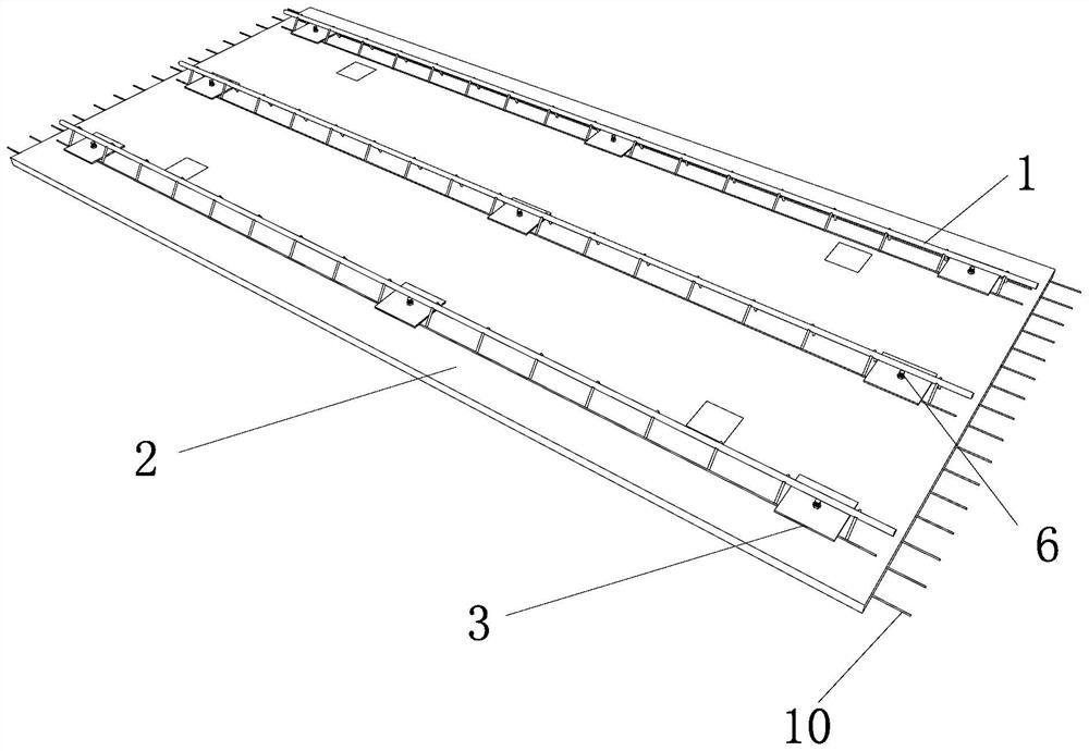
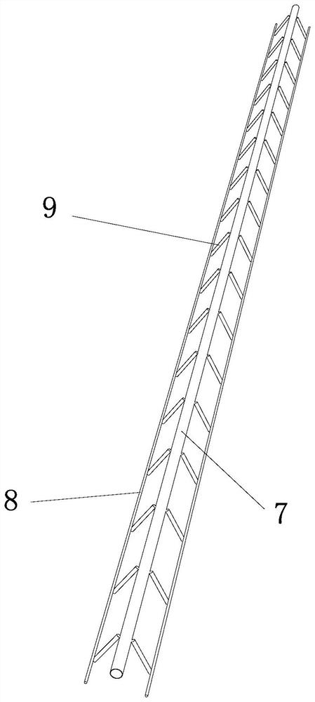
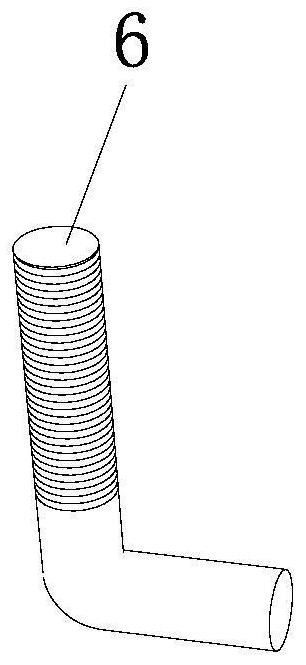
[0039] See attached figure 1 to attach Figure 4 The present embodiment is a prestressed thin plate with a detachable rib 1, including a prestressed bottom plate 2, at least two detachable ribs 1 and a plurality of connecting components, and the detachable rib 1 includes an upper chord 7 and a lower steel bar 8 And the web 9, two lower steel bars 8 and an upper chord 7 are fixedly connected through the web 9; the connecting assembly includes a fixing plate 3, a fixing piece and a connecting piece, the connecting piece includes a first end and a second end, and the connecting The first end of the piece is anchored in the prestressed bottom plate 2, the second end of the fixed piece exposes the prestressed bottom plate 2, passes through the fixed plate 3 and is fixed on the fixed plate 3 through the connecting piece; the lower steel bar 8 is placed on the prestressed bottom plate 2 The surface of the fixed plate 3 spans the two lower steel bars 8, and the connecting piece is ar...

Embodiment 2

[0050] See attached figure 1 to attach Image 6 The present embodiment is a construction method of a laminated slab, the laminated slab includes the prestressed thin slab and the cast-in-place layer in Embodiment 1, and the concrete of the cast-in-place layer is poured on the surface of the prestressed floor 2 away from the detachable rib 1 , specifically include the following steps:

[0051] S1 production of prestressed thin plates: place prestressed steel bars 10 and ordinary steel bars in the production mold, connect and fix the first end of the connector with prestressed steel bars 10 or ordinary steel bars, place the embedded parts and connectors, and the first end of the connectors The height of the two ends is higher than the thickness of the prestressed base plate 2, the detachable rib 1 is placed, the fixed plate 3 is clamped between the two lower steel bars 8, and the second end of the connector is located between the two lower steel bars 8, passing through the fixe...


PUM


Abstract

The invention relates to a construction method of a prestressed thin plate and a laminated plate with detachable ribs. The prestressed thin plate comprises a prestressed bottom plate, the detachable ribs and connecting assemblies, the detachable ribs comprise upper chords, lower steel bars and web members, and the two lower steel bars and one upper steel bar are fixed through the plurality of web members; the connecting assembly comprises a fixing plate, a fixing piece and a connecting piece, the first end of the connecting piece is anchored in the prestressed bottom plate, and the second end of the fixing piece is exposed out of the prestressed bottom plate and fixed to the fixing plate through the connecting piece; the lower steel bars are placed on the surface of the prestress bottom plate, the fixing plate stretches across the two lower steel bars, and the connecting piece is arranged between the two lower steel bars. The laminated slab comprises the prestressed thin slab and a cast-in-place layer, concrete of the cast-in-place layer is poured on the surface, away from the detachable ribs, of the prestressed bottom plate, the construction method comprises the steps that S1, the prestressed thin plate is produced; S2, the cast-in-place layer is poured; and S3, dismantling is conducted. The prestressed thin plate is large in span, small in thickness, not prone to cracking and high in transportation efficiency.

Description

technical field [0001] The invention belongs to the technical field of prefabricated buildings, and in particular relates to a construction method of a prestressed thin plate with detachable ribs and a laminated plate. Background technique [0002] The laminated floor is the most widely used prefabricated component in prefabricated buildings, but the commonly used truss reinforced laminated floor has problems such as high steel content, large floor thickness, many on-site installation supports, and difficulty in supporting formwork with two-way slabs. Due to the above reasons, its comprehensive cost is much higher than that of cast-in-place slabs. [0003] The emergence of prestressing technology can effectively reduce the content of steel bars and control the occurrence of cracks in the floor slab. However, when the thickness of the prestressed laminated floor is small, it is easy to have problems such as arching and insufficient overall rigidity. It is often necessary to c...

Claims


Application Information

Patent Timeline
IPC IPC(8): E04B5/29B28B23/04
CPCE04B5/29B28B23/04
Inventor 陈甫亮田宝晴施明哲
Owner 筑友智造建设科技集团有限公司
Why Eureka
Try Eureka