Method for confirming sheet stamping member measuring point cloud position before rebound based on finite element method

A thin-plate stamping and finite element technology, which is applied in the field of thin-plate stamping and forming, can solve the problems of unguaranteed precision and long time

Inactive Publication Date: 2009-07-15
HUNAN UNIV
View PDF0 Cites 30 Cited by
  • Summary
  • Abstract
  • Description
  • Claims
  • Application Information

AI Technical Summary

Problems solved by technology

Due to the large number of points, the process ta

Method used


Image

  • Method for confirming sheet stamping member measuring point cloud position before rebound based on finite element method
  • Method for confirming sheet stamping member measuring point cloud position before rebound based on finite element method
  • Method for confirming sheet stamping member measuring point cloud position before rebound based on finite element method

Examples


Embodiment Construction

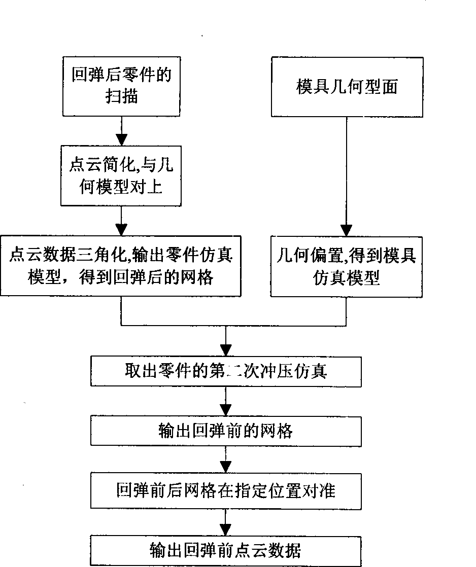
[0022] Using the point cloud data processing method proposed by the present invention, the point cloud data simplification program, the program corresponding to point cloud data and digital model, and the point cloud triangulation program have been developed, and the calculation examples are completed by using LSDYNA software and DYNAFORM software.

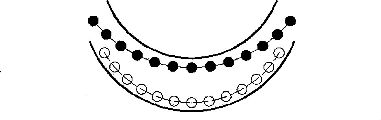
[0023] First, simplify the point cloud data, and take 1 point every 3mm or so. Align the simplified point cloud data with the geometric model of the part. The method of alignment is as follows: find three points in the digital model, such as points with obvious geometric features on the part, such as hollow centers, bosses, edges and corners, etc., and the positions of these points in the point cloud can also be determined. According to the corresponding point, the point cloud can be placed near the geometric model, and then, through the coincidence of one edge, the position of the part can be further determined, and through the t...


PUM


Abstract

The invention relates to a method for determining the position of the measurement point cloud of the sheet stamping workpiece before rebound based on finite element method. The method comprises: transferring the point cloud data to the corresponding position in a geometric model; converting the data cloud data into triangle or quadrangle grids, and outputs into a finite element input format file to obtain the grid of sheet material; establishing simulation model according to the actual mould profile to obtain the mould profile grids; establishing a simulation model according to the mould and sheet material grids, and pressing the rebounded grid reversely the position before rebound; and outputting the nodes in the finite element to obtain the position of the measurement point cloud before rebound. Applying the invention can determine the rebounded compensation profile or the edge trimming line on the rebounded workpiece rapidly and accurately.

Description

technical field [0001] The invention relates to the field of stamping and forming of a set of thin plates, in particular to a method for determining the position of a measurement point cloud of a thin plate stamping part before springback based on a finite element method. Background technique [0002] The car body is mainly thin sheet stamping parts. In order to improve the safety of the car body and reduce the weight of the car body, more and more high-strength steels are used in auto body parts, and the problem of stamping springback of high-strength steels is particularly prominent. The so-called springback refers to the release of elastic stress in the stamping part when the part is withdrawn from the stamping die, causing the deformation of the part. The parts after springback no longer match the geometric profile of the mold. If the profile is processed according to the geometric model of the part, the springback will cause the dimensional accuracy of the stamped part...

Claims


Application Information

Patent Timeline
IPC IPC(8): G01B21/00G01B21/32G06T17/20
Inventor 刘迪辉李光耀龚志辉崔向阳
Owner HUNAN UNIV
Why Eureka
Try Eureka