
Electronic tag wireless data transmission current sensor

A current sensor and electronic label technology, applied in the field of sensors, can solve the problems of affecting stability, consuming a lot of time, and low maintenance efficiency, and achieving the effect of avoiding prolapse, improving the efficiency of disassembly and maintenance, and ensuring stability.

Inactive Publication Date: 2022-01-14
SHENZHEN HUAYIFENG TECH CO LTD
View PDF0 Cites 2 Cited by
  • Summary
  • Abstract
  • Description
  • Claims
  • Application Information

AI Technical Summary

Problems solved by technology

[0002] In the process of wireless data transmission of electronic tags, the data transmission equipment needs to use a current sensor. The current sensor is a detection device that can sense the information of the measured current, and can transform the information sensed by the detection according to a certain rule. It becomes an electrical signal that meets certain standards or other required forms of information output to meet the requirements of information transmission, processing, storage, display, recording and control. Most of the commonly used current sensors are fixed and non-detachable structures. Therefore, it takes a lot of time to disassemble and assemble. When the current sensor fails and needs to be disassembled for maintenance or replacement, it takes more time for disassembly. The maintenance efficiency is low, and the bolts and other structures are disassembled many times. Installing will affect the stability and cause inconvenience

Method used


Image

  • Electronic tag wireless data transmission current sensor
  • Electronic tag wireless data transmission current sensor
  • Electronic tag wireless data transmission current sensor

Examples


Embodiment Construction

[0025] In order to make the technical means, creative features, goals and effects achieved by the present invention easy to understand, the present invention will be further described below in conjunction with specific embodiments.

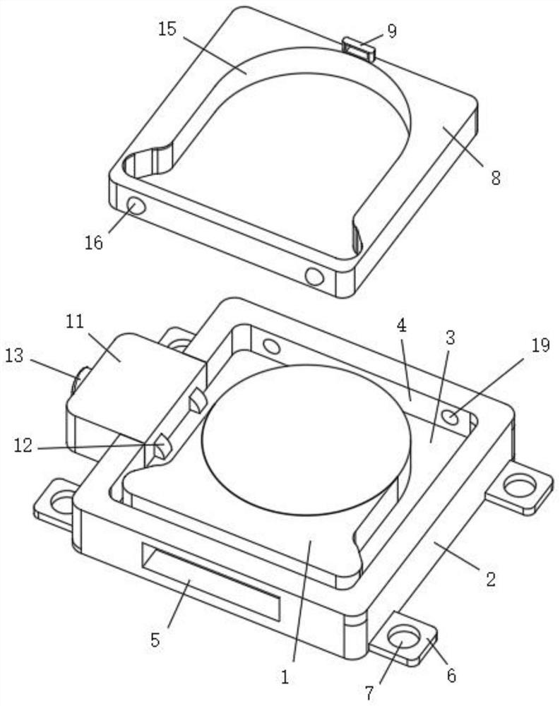
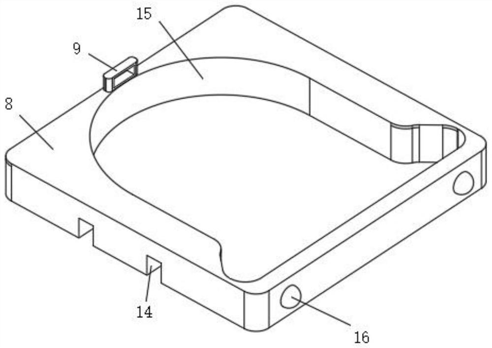
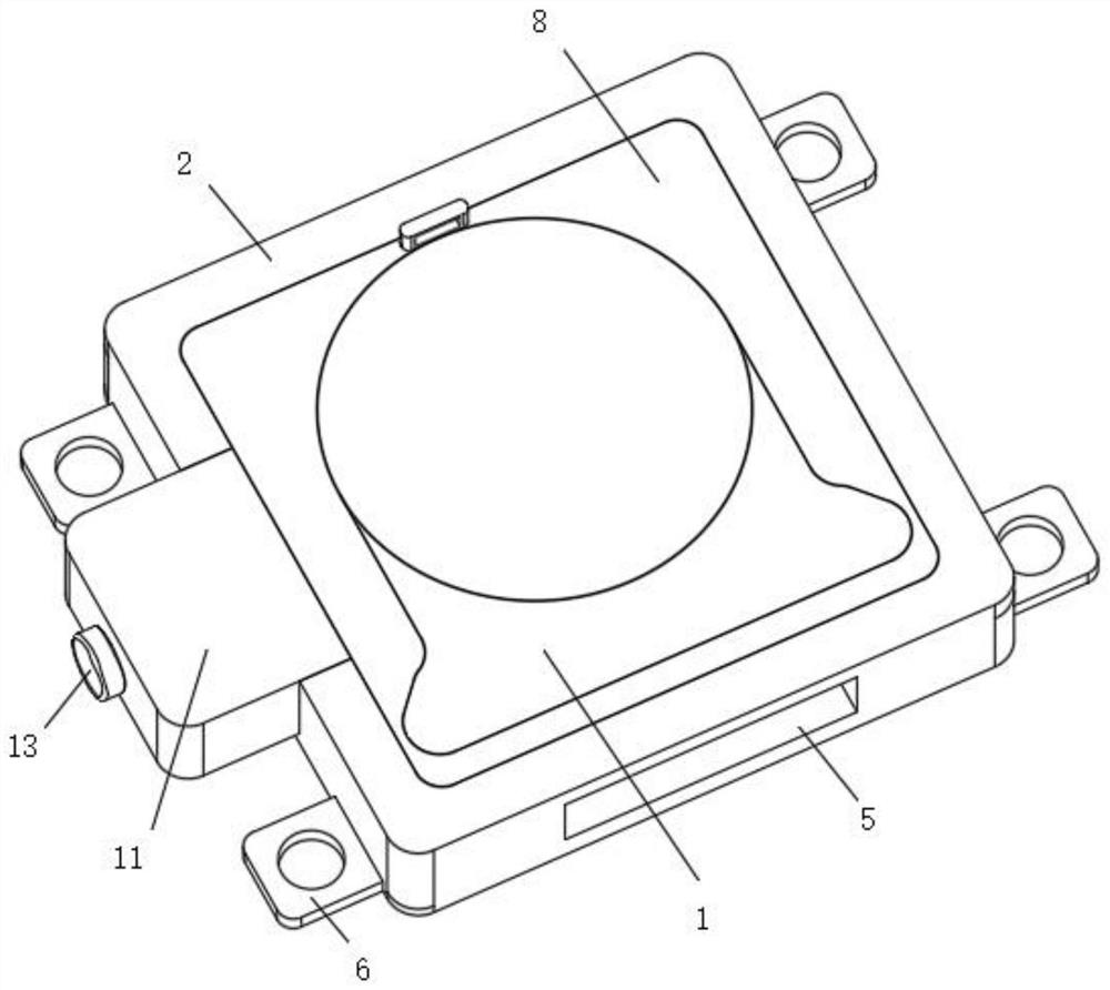
[0026] Such as Figure 1-7 As shown, an electronic tag wireless data transmission current sensor includes a sensor body 1 and a fixing seat 2, a bottom plate 3 is arranged under the sensor body 1, a fixing groove 4 is arranged on the upper end surface of the fixing seat 2 corresponding to the bottom plate 3, and the top of the fixing groove 4 An adjustable top cover 8 is provided, and the inner ring of the top cover 8 is provided with an embedding groove 15 corresponding to the sensor body 1. The upper end surface of the top cover 8 is provided with a buckle 9 at the head position, and the inner wall on one side of the fixing groove 4 is provided with a built-in block. 11. There are two adjustable self-locking pressing blocks 12 on the inner side ...


PUM


Abstract

The invention discloses an electronic tag wireless data transmission current sensor. The sensor comprises a sensor main body and a fixing seat, wherein a bottom plate is arranged below the sensor main body, a fixing groove corresponding to the bottom plate is formed in an upper end surface of the fixing seat, and an adjustable top cover is arranged at the top of the fixing groove; a clamping groove is formed in the position, corresponding to the sensor body, of an inner ring of the top cover, a buckle is arranged at the head position of an upper end face of the top cover, a built-in block is arranged on an inner wall of one side of the fixing groove, two adjustable self-locking pressing blocks are arranged on an end face of the inner side of the built-in block, and the self-locking pressing blocks are located above the bottom plate; and an adjustable movable pulling plate is arranged on an outer side end face of the built-in block. The invention relates to an electronic tag wireless data transmission current sensor, which belongs to the field of sensors, and is characterized in that a fixing seat is mounted below the sensor, the built-in block is arranged on one side of the fixing seat, and an adjustable self-locking pressing block is mounted by using the built-in block for fixation so that the sensor is more rapid to disassemble and assemble and convenient to overhaul and maintain.

Description

technical field [0001] The invention relates to the field of sensors, in particular to an electronic tag wireless data transmission current sensor. Background technique [0002] In the process of wireless data transmission of electronic tags, the data transmission equipment needs to use a current sensor. The current sensor is a detection device that can sense the information of the measured current, and can transform the information sensed by the detection according to a certain rule. It becomes an electrical signal that meets certain standards or other required forms of information output to meet the requirements of information transmission, processing, storage, display, recording and control. Most of the commonly used current sensors are fixed and non-detachable structures. Therefore, it takes a lot of time to disassemble and assemble. When the current sensor fails and needs to be disassembled for maintenance or replacement, it takes more time for disassembly. The maintena...

Claims


Application Information

Patent Timeline
Patent Type & Authority Applications(China)
IPC IPC(8): G01R19/00G01R15/00
CPCG01R19/0092G01R15/00
Inventor 张小毅罗超凡
Owner SHENZHEN HUAYIFENG TECH CO LTD
Learn More