Hardware stamping die

A stamping die and hardware technology, applied in the direction of perforating tools, manufacturing tools, metal processing equipment, etc., can solve the problems of needing manual assistance, unable to adjust the distance between punching holes, etc., and achieve the effect of convenient feeding

Pending Publication Date: 2022-01-18
郭舒宇
View PDF0 Cites 0 Cited by
  • Summary
  • Abstract
  • Description
  • Claims
  • Application Information

AI Technical Summary

Problems solved by technology

[0004] Aiming at the deficiencies of the prior art, the present invention provides a metal stamping die, which solves the problems that the metal stamping die needs manual assistance in the stamping process and cannot adjust the adjacent distance of punching holes

Method used


Image

  • Hardware stamping die
  • Hardware stamping die
  • Hardware stamping die

Examples


Embodiment Construction

[0036] The following will clearly and completely describe the technical solutions in the embodiments of the present invention with reference to the accompanying drawings in the embodiments of the present invention. Obviously, the described embodiments are only some, not all, embodiments of the present invention. Based on the embodiments of the present invention, all other embodiments obtained by persons of ordinary skill in the art without making creative efforts belong to the protection scope of the present invention.

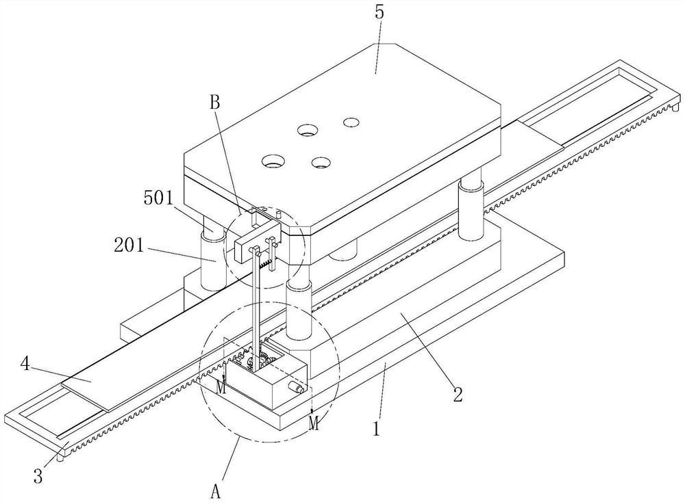
[0037] Such as Figure 1-10 As shown, the embodiment of the present invention provides a metal stamping die, including a base 1, a lower mold base 2, an upper mold base 5, a sliding plate 3 and a stamping workpiece 4;

[0038] The outer wall of the top of the base 1 is fixedly connected with a lower mold base 2, the top of the lower mold base 2 is movably connected with a sliding plate 3, the outer wall of the top of the sliding plate 3 is provided with a stam...


PUM


Abstract

The invention relates to the field of dies, and particularly relates to a hardware stamping die. The hardware stamping die comprises a base, a lower die base, an upper die base, a sliding plate and a stamping workpiece; the outer wall of the top of the base is fixedly connected with the lower die base; the top of the lower die base is movably connected with the sliding plate; the stamping workpiece is arranged on the outer wall of the top of the sliding plate; the upper die base is arranged on the top of the stamping workpiece; the periphery of the outer wall of the top of the lower die base is fixedly connected with lower guide columns; the positions, corresponding to the lower guide columns, of the outer wall of the bottom of the upper die base are fixedly connected with upper guide columns; and the lower guide columns and the upper guide columns are movably connected. In order to facilitate movement of the stamping workpiece on the sliding plate, a long strip is arranged in the sliding plate, balls in the long strip make contact with the stamping workpiece through adjustment of adjusting bolts, and feeding of the stamping workpiece is facilitated; and after the stamping workpiece is positioned, the long strip is moved downwards through adjustment of the adjusting bolts, the balls do not make contact with the stamping workpiece any more, and feeding of the stamping workpiece is facilitated.

Description

technical field [0001] The invention relates to the field of molds, in particular to a metal stamping mold. Background technique [0002] Stamping die is a special process equipment for processing materials (metal or non-metal) into parts (or semi-finished products) in cold stamping processing. It is called cold stamping die (commonly known as cold stamping die). Stamping is at room temperature. A pressure processing method that uses a mold installed on a press to apply pressure to the material to cause separation or plastic deformation to obtain the required parts, and hardware refers to metals such as gold, silver, copper, iron, and tin. Tools obtained through processing and casting are used to fix things, process things, decorate, etc. Usually, metal parts need stamping dies to assist in punching them during processing. [0003] The problems existing in the existing metal stamping dies are: 1. The stamping die mainly punches the material on the hardware through the punch...

Claims


Application Information

Patent Timeline
IPC IPC(8): B21D28/34B21D28/26B21D43/05B21D43/13
CPCB21D28/34B21D28/26B21D43/05B21D43/13
Inventor 郭舒宇陈杰
Owner 郭舒宇
Why Eureka
Try Eureka