Detection tool and detection system for electric meter detection
A technology for testing tooling and testing systems, which is applied in the direction of measuring devices, measuring electrical variables, instruments, etc., can solve the problems of only being eliminated, low efficiency, complex structure, etc., and achieves saving line change time and investment costs, and interchangeability And the effect of strong versatility, interchangeability and versatility
- Summary
- Abstract
- Description
- Claims
- Application Information
AI Technical Summary
Problems solved by technology
Method used
Image
Examples
Embodiment 1
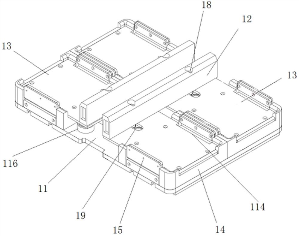
[0041] like figure 1As shown, in this embodiment, a detection tool for electric meter detection includes an installation base plate 11, an A stopper 12 arranged on the installation base plate 11, and several pieces are arranged on the installation base plate 11 and are located between the A stopper 12 and the installation base plate 11. The meter placement plate 13 on the side, several B blocks 14 arranged on the installation base plate 11, the A block 12 and the B block 14 are respectively located on the opposite sides of the meter placement plate 13, and the other side of the meter placement plate 13 Sliding baffles 15 slidably connected to the installation base 11 are provided on both sides.
[0042] The ammeter is placed on the ammeter placement plate 13, and the ammeter is clamped by controlling the two sliding baffles 15 to slide towards each other. The A block 12 and the B block 14 can block the ammeter from both sides that are not clamped, thereby limiting the ammeter...
Embodiment 2
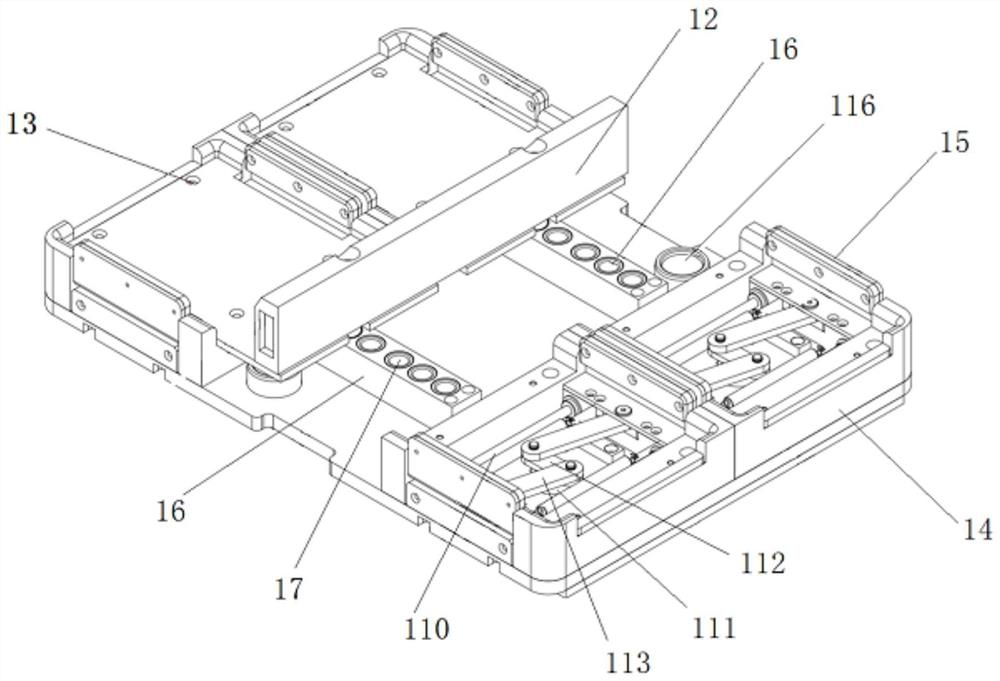
[0047] like figure 2 As shown, on the basis of the above embodiments, in this embodiment, the installation base 11 is provided with two adjustment supports 16 perpendicular to the A block 12, and the adjustment supports 16 are arranged at equal intervals. There are several pin holes 17, and the A stopper 12 is provided with a pin 18 that is fitted in cooperation with the pin holes 17.
[0048] Utilize the pin 18 and the pin hole 17 of different positions to cooperate to install, can adjust the position of A stopper 12, thereby change the distance between A stopper 12 and B stopper 14, with this according to the electric meter of different size to A stopper 12 The position is adjusted to increase the scope of application of the detection tool.
[0049] Making the length direction of the adjustment support 16 perpendicular to the length direction of the A block 12 can ensure the position accuracy of the A block 12 before and after adjustment.
[0050] In this embodiment, the ...
Embodiment 3
[0053] On the basis of the above embodiments, in this embodiment, two spring adjustment structures 110 are connected between the two sliding baffles 15 on both sides of the same meter placement plate 13, and the spring adjustment structures 110 are located on the meter placement plate 13 Below, the spring in the spring adjustment structure 110 is provided with a stretched spring.
[0054] The tensioned springs are used to exert an inward pulling force on the two sliding baffles 15 , so as to provide a clamping force on the ammeter, so that the two sliding baffles 15 can clamp the ammeter. In addition, the distance between the two sliding baffles 15 can be adaptively adjusted according to the size of the electric meter, thereby increasing the scope of application of the detection tool.
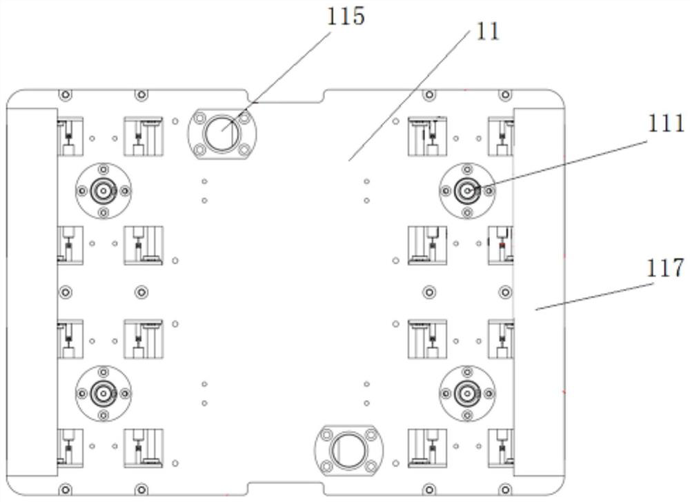
[0055] like image 3 As shown, in this embodiment, the installation bottom plate 11 is provided with a rotating shaft 111 below the electric meter placement plate 13, and the top of the rotati...
PUM
 Abstract
Description
Claims
Application Information
 - R&D
- Intellectual Property
- Life Sciences
- Materials
- Tech Scout
- Unparalleled Data Quality
- Higher Quality Content
- 60% Fewer Hallucinations
Browse by: Latest US Patents, China's latest patents, Technical Efficacy Thesaurus, Application Domain, Technology Topic, Popular Technical Reports.
© 2025 PatSnap. All rights reserved.Legal|Privacy policy|Modern Slavery Act Transparency Statement|Sitemap|About US| Contact US: help@patsnap.com


