Electrical cabinet with overheating protection structure

A technology for overheating protection and electrical cabinets, applied in the field of electrical cabinets, can solve the problems of cooling internal components and the difficulty of timely and effective discharge of high temperature in electrical cabinets, and achieves the effect of preventing moisture and having effective effects.

Pending Publication Date: 2022-01-18
浙江辉博电力设备制造有限公司
View PDF0 Cites 0 Cited by
  • Summary
  • Abstract
  • Description
  • Claims
  • Application Information

AI Technical Summary

Problems solved by technology

[0004] The purpose of the present invention is to provide an electrical cabinet with an overheating protection structure, which solves the problem that the internal high temperature of the electrical cabinet in the prior art is difficult to be discharged in time and effectively and the internal components are cooled during use.

Method used


Image

  • Electrical cabinet with overheating protection structure
  • Electrical cabinet with overheating protection structure
  • Electrical cabinet with overheating protection structure

Examples


Embodiment 1

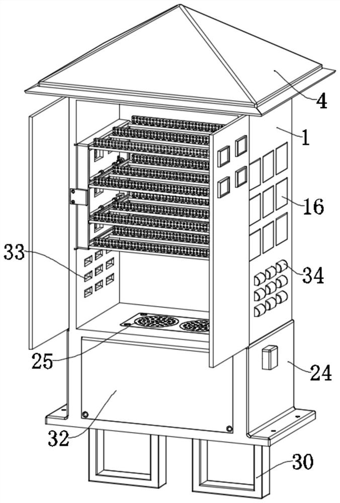
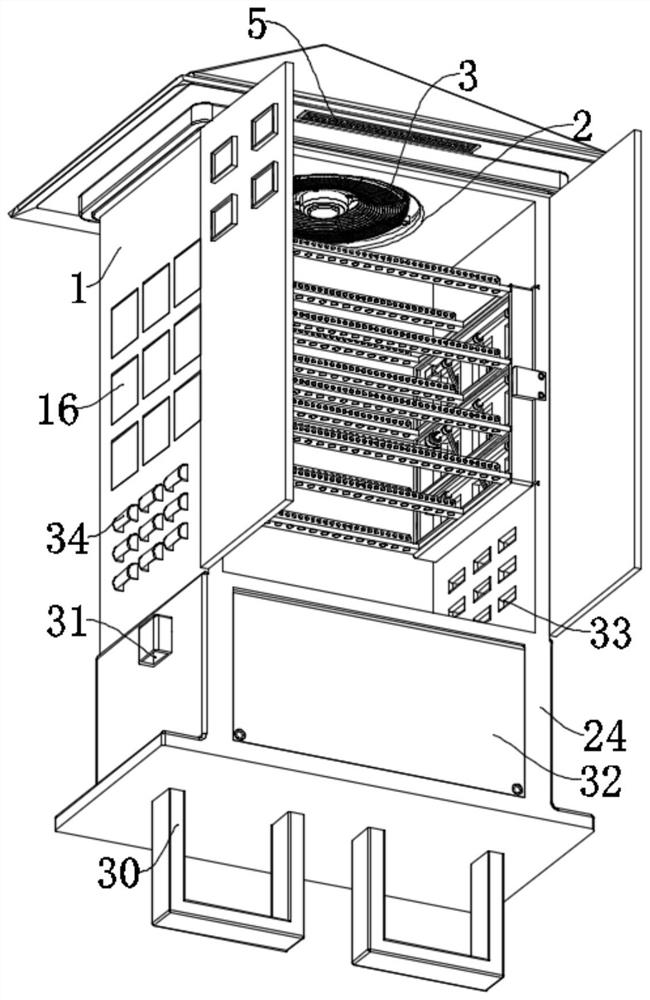
[0033] refer to Figure 1-8 , an electrical cabinet with an overheating protection structure, comprising an electrical cabinet 1, a first heat dissipation mechanism is provided on the top of the electrical cabinet 1, the first heat dissipation mechanism includes a top cover 4 arranged on the top of the electrical cabinet 1, and the top of the top cover 4 is pointed shape, the surface is inclined, which is convenient for outdoor use to block and disperse rainwater drainage, and the top cover 4 is provided with a cavity inside to accommodate gas, and the bottom of the electrical cabinet 1 is provided with air inlets 5 at the front and rear positions. The air inlet 5 enters the inside of the cavity when the external air enters, and the inside of the air inlet 5 is provided with a first dust-proof net, which prevents the dust from the outside from entering the cavity. The top of the electrical cabinet 1 is provided with a The installation groove 2 connected with the cavity, the in...

Embodiment 2

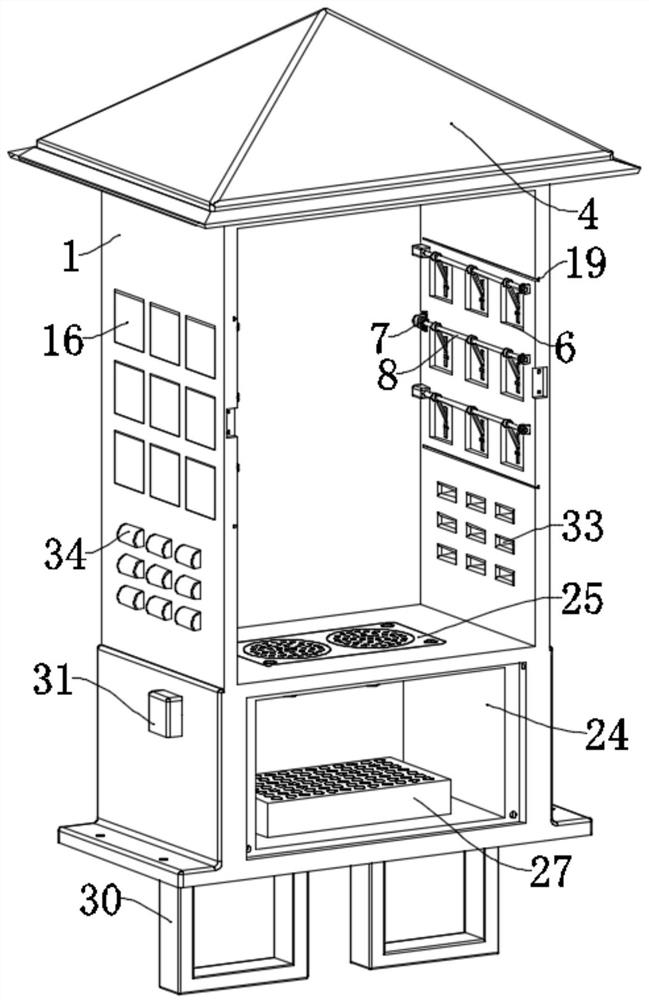
[0040] refer to Figure 1-8 , an electrical cabinet with an overheat protection structure, the bottom of the electrical cabinet 1 is fixed with a cold air box 24, the cold air box 24 is convenient for containing cold air, and a second heat dissipation fan is connected between the cold air box 24 and the electrical cabinet 1 26. The second heat dissipation fan 26 is convenient for sucking cold air into the interior of the cold air box 24. The top of the second heat dissipation fan 26 is located at the bottom of the inside of the electrical cabinet 1 and is provided with a filter plate 25. The filter plate 25 prevents components or routes from interfering with the second heat dissipation fan. 26 internal contacts, to prevent damage to the second cooling fan 26, the inside of the air-conditioning box 24 both sides is provided with an air chamber, and the air-conditioning box 24 both sides are provided with an air intake pipe 31 communicating with the air chamber, and the air intak...


PUM


Abstract

The invention relates to the technical field of electrical cabinets, in particular to an electrical cabinet with an overheating protection structure, and solves the problems that internal high temperature is not easy to timely and effectively discharge and internal components are not easy to cool when an electrical cabinet in the prior art is used. The electrical cabinet specifically comprises an electrical cabinet, multiple sets of first heat dissipation openings are formed in the two sides of the electrical cabinet in a penetrating mode, blocking pieces are rotationally arranged in the first heat dissipation openings, driving assemblies are arranged on the opposite faces in the electrical cabinet, the driving assemblies are movably connected with the blocking pieces through linkage pieces, and protection frames are arranged on the opposite faces in the electrical cabinet. A plurality of groups of mounting pieces are arranged between the protection frames up and down, and a plurality of groups of second heat dissipation openings are formed in the two sides of the electrical cabinet and located below the first heat dissipation openings in a penetrating mode. A stop block is arranged at the second heat dissipation opening. According to the invention, the interior of the electrical cabinet can be timely and effectively cooled, normal use of the electrical cabinet can be conveniently recovered, and damage to components of the electrical cabinet, even safety accidents such as fire disasters caused by high temperature in the electrical cabinet during use can be prevented.

Description

technical field [0001] The invention relates to the technical field of electrical cabinets, in particular to an electrical cabinet with an overheating protection structure. Background technique [0002] Electrical cabinets are mainly used in chemical industry, environmental protection industry, power system, metallurgical system, industry, nuclear power industry, fire safety monitoring, transportation industry, etc. It is a cabinet made of steel to protect components and circuits from normal operation. When the electrical cabinet is in use, due to the large number of internal electrical components, the electrical components will generate relatively large heat during long-term use. Heat dissipation, and some electrical cabinets are equipped with overheating protectors. When the heat inside the cabinet is too high to dissipate heat in time, in order to prevent the internal components and lines of the electrical cabinet from being damaged due to high temperature, or even a fire...

Claims


Application Information

Patent Timeline
IPC IPC(8): H02B1/56H02B1/28H02B1/30H02B1/32
CPCH02B1/56H02B1/28H02B1/30H02B1/32Y02A30/14
Inventor 徐余丰何建明周起明琚正伟吴德胜沈强潘宇
Owner 浙江辉博电力设备制造有限公司
Why Eureka
Try Eureka