Floor tile laying equipment capable of preventing concrete drying for building decoration

A technology for concrete and floor tiles, which is used in construction, building structure, clay preparation devices, etc., can solve the problems of easy drying of concrete and long time, and achieve the effect of improving the laying effect, preventing the drying of concrete and ensuring the adhesion.

Pending Publication Date: 2022-01-21
杨小龙
View PDF10 Cites 2 Cited by
  • Summary
  • Abstract
  • Description
  • Claims
  • Application Information

AI Technical Summary

Problems solved by technology

[0004] Based on this, it is necessary to address the above problems, to propose a building decoration that can automatically add concrete to the floor tiles to facilitate laying, can automatically lay bricks on the ground, and can effectively prevent the concrete from drying out. floor tile laying equipment, in order to solve the prior art proposed in the background technology above, the time required for manual laying is relatively long, and the concrete is easy to dry out

Method used


Image

  • Floor tile laying equipment capable of preventing concrete drying for building decoration
  • Floor tile laying equipment capable of preventing concrete drying for building decoration
  • Floor tile laying equipment capable of preventing concrete drying for building decoration

Examples


Embodiment 1

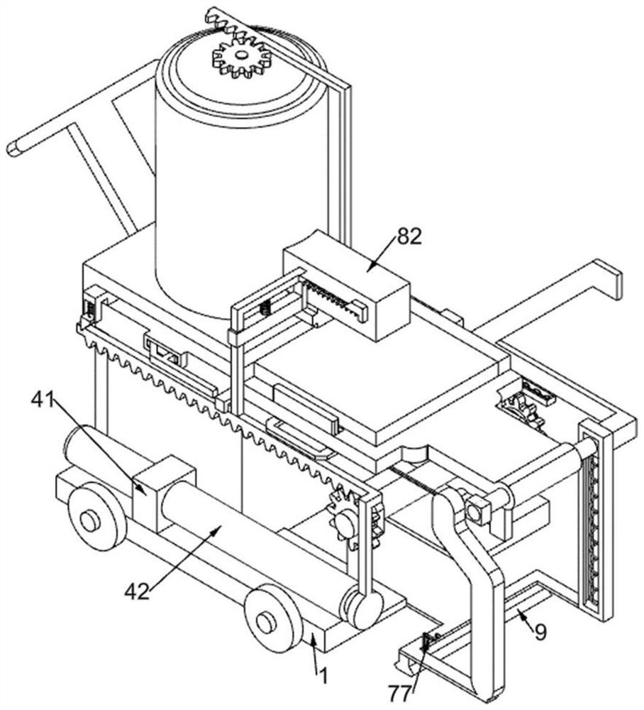
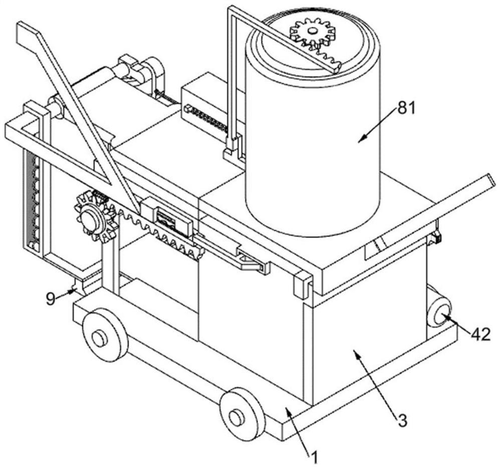
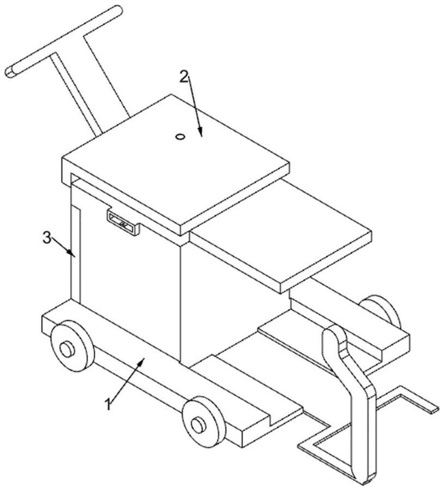
[0038] A floor tile laying equipment that can prevent concrete from drying out for building decoration, such as Figure 1-11 As shown, it includes a sliding loading vehicle 1, a slotted push frame 2, a cover plate 3, a driving mechanism 4, a pushing mechanism 5, a turning brick laying mechanism 6, and a clamping reset mechanism 7. The sliding loading vehicle 1 is rectangular. Distributed with four rollers, the top of the sliding loading car 1 is fixed with a slotted push frame 2, and the slotted push frame 2 is connected with a cover plate 3 through a hinge, and the cover plate 3 is connected with the slotted push frame 2 and the sliding loading plate The car 1 contacts, and the sliding loading car 1 is provided with a driving mechanism 4 for driving the operation of the equipment, and the slotted push frame 2 is provided with a pushing mechanism 5 for pushing the floor tiles inside the slotted pushing frame 2, and the sliding loading car 1 is provided with an overturning bric...

Embodiment 2

[0048] On the basis of Example 1, such as Figure 12 As shown, it also includes a discharge rotating mechanism 8, which is used to add concrete to the surface of the floor tiles on the turnover plate 63. , rectangular cavity block 82, baffle plate 83, ninth return spring 84, special-shaped push block 85, wedge-shaped slide bar 86, tenth return spring 87, eleventh return spring 88, L-shaped rack frame 89, third gear 810 and turbine rod 811, the outer top of the slotted push frame 2 is fixedly connected with a cylinder 81, the cylinder 81 is cylindrical, and its interior is a cavity structure, and the outer wall of the cylinder 81 is connected with a rectangular cavity block 82, the rectangular cavity block 82 The inside of cavity block 82 is a cavity structure, and its bottom has a rectangular hole. The bottom of rectangular cavity block 82 is slidably connected with baffle plate 83. The ninth back-moving spring 84 that plate 83 resets, the rectangular cavity block 82 is slida...

Embodiment 3

[0051] On the basis of Example 2, such as figure 1 As shown, a flattening block 9 is also included, and the bottom of the sliding loading vehicle 1 is fixedly connected with the flattening block 9, and the flattening block 9 is located below the turning plate 63.

[0052] Then manually push the sliding pallet loading vehicle 1 and its upper device to continue to move forward. The laid floor tiles can be flattened by the flattening block 9. Finally, the electric push rod 42 is manually controlled to stop operation. Repeat the above operations to use the equipment to lay floor tiles again. .


PUM


Abstract

The invention relates to the field of building decoration, in particular to floor tile laying equipment capable of preventing concrete drying for building decoration. The floor tile laying equipment comprises a sliding plate loading vehicle, a slotting push frame, a cover plate, a driving mechanism and the like, the top of the sliding plate loading vehicle is fixedly provided with the slotting push frame, and the slotting push frame is connected with the cover plate through a hinge; and the cover plate makes contact with the slotting push frame and the sliding plate loading vehicle, and a driving mechanism is arranged on the sliding plate loading vehicle. According to the floor tile laying equipment capable of preventing concrete drying for building decoration, through cooperation of a turbine rod and devices on the turbine rod, the turbine rod can stir concrete in a cylinder and prevent the concrete in the cylinder from being dried, so that the adhesion degree of the concrete in the cylinder can be guaranteed, the subsequent floor tile laying effect can be improved, and the purpose of effectively preventing the concrete in the cylinder from being dried is achieved.

Description

technical field [0001] The invention relates to the field of building decoration, in particular to a floor tile laying device for building decoration that can prevent concrete from drying out. Background technique [0002] Architectural decoration can protect the main structure of the building. At the same time, architectural decoration can beautify the building and improve the space quality of the building. Therefore, architectural decoration is an indispensable part of modern construction projects. Floor tiles are a kind of ground decoration materials. Floor tiles are used as a large-area The laid floor material can use its own color and texture to create a living environment with different styles. Therefore, most users will beautify the main body of the building and create a comfortable living environment by laying floor tiles. [0003] The method of laying floor tiles usually needs to prepare concrete, then add concrete to one side of the floor tiles, and then place the ...

Claims


Application Information

Patent Timeline
Patent Type & Authority Applications(China)
IPC IPC(8): E04F21/22E04F21/20E04F21/02B28C5/16B28C9/04
CPCE04F21/22E04F21/20E04F21/023B28C5/16B28C9/04
Inventor 杨小龙
Owner 杨小龙
Why Eureka
Try Eureka