Optical system fixed through UV glue and lamp thereof

An optical system and glue column technology, applied in the field of optical systems and their lamps, can solve the problems of great influence on installation operability, difficulty in ensuring operability, product design restrictions, etc., achieving easy operation, unchangeable positioning, The effect of space flexibility

Pending Publication Date: 2022-01-21
MAGNETI MARELLI AUTOMOTIVE COMPONENTS WUHU
View PDF1 Cites 0 Cited by
  • Summary
  • Abstract
  • Description
  • Claims
  • Application Information

AI Technical Summary

Problems solved by technology

[0004] The traditional installation method requires enough space for the product itself to design the matching structure, which limits the design of the product itself
During the installation process, the product structure has a great influence on the operability of the installation. It is difficult to ensure the operability while satisfying the structure of the product performance.
Especially for systems with higher requirements on the optical precision of the optical system, the disadvantages of the existing positioning and fastening methods are more obvious, even if the deviation is small, the defects in the final rendering effect will be seriously magnified

Method used


Image

  • Optical system fixed through UV glue and lamp thereof
  • Optical system fixed through UV glue and lamp thereof
  • Optical system fixed through UV glue and lamp thereof

Examples


Embodiment 1

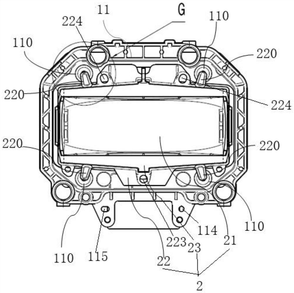
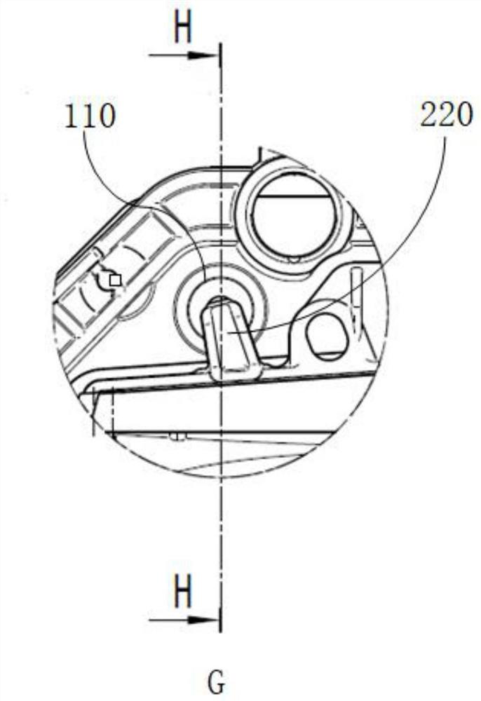
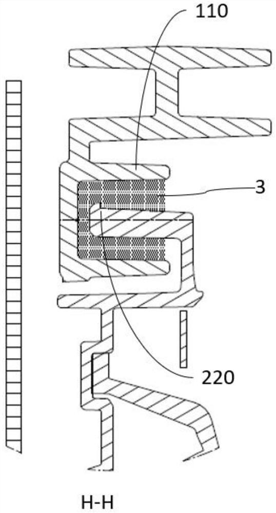
[0048] According to an optical system fixed by UV glue provided by the present invention, it includes a circuit board device 1 and a lens device 2, and the circuit board device 1 and the lens device 2 are bonded and fixed by UV glue 3 to form an optical system as a whole .

[0049]The circuit board device 1 includes a bracket 11 and a PCB board 12, the PCB board 12 includes a PCB board body 121, LED light emitting diodes 122, round holes 123, waist holes 124 and screw posts 125, and a plurality of LED light emitting diodes 122 arrays are distributed on the PCB board Preferably, 84 LED light emitting diodes are used on the body 121 . The round holes 123 and the waist holes 124 are respectively distributed around the PCB body 121 , and the round holes 123 are fitted and connected with the first positioning pins 111 on the bracket 11 one by one. Preferably, the round hole 123 and the first positioning pin 111 serve as the first positioning reference. The waist holes 124 are fit...

Embodiment 2

[0066] The invention also provides a lamp, which includes an optical system fixed by UV glue.


PUM


Abstract

The invention provides an optical system fixed through UV glue and a lamp thereof, which relate to the technical field of automobile lamps. The optical system comprises a circuit board device and a lens device, and the circuit board device and the lens device are bonded into a whole through the UV glue; the circuit board device comprises a support and a PCB, and the PCB is connected with the support in a matched mode. The lens device comprises a lens assembly, an adapter and a spring, and the lens assembly is connected to the adapter through the spring; the glue storage columns on the support are filled with the UV glue, the circuit board device and the lens device are subjected to limiting tooling through the tooling clamp, and the installation corners are fixed in the glue storage columns through the UV glue. By adopting a tool positioning mode, the influence of part deformation on a positioning system is solved, and the relative subpackage position is directly determined from a test terminal. By means of the UV glue ultraviolet curing mode, the problem that in a traditional fastening scheme, precision is difficult to guarantee is solved, it is guaranteed that position changes cannot be generated in the installation process and after installation is completed, and the high-precision assembly requirement is met.

Description

technical field [0001] The invention relates to the technical field of automobile lamps, in particular to an optical system fixed by UV glue and a lamp thereof. Background technique [0002] The traditional positioning method between the two sub-packaging systems of the optical system is the positioning of the sub-assembly product structure, but the accumulation of the respective dimensional chains of the two sub-packaging systems will lead to a long dimensional chain, and the total distance between the LED light-emitting diode and the optical lens Accuracy cannot be guaranteed. With the continuous innovation and development of car light technology, the precision requirements of the car light optical system have increased by orders of magnitude. The emergence of the ADB adaptive high beam function has accelerated the high-precision requirements of the optical system. The above-mentioned existing positioning methods are due to size chains, etc. The problem is that when deali...

Claims


Application Information

Patent Timeline
Patent Type & Authority Applications(China)
IPC IPC(8): G02B7/02F21V17/10F21W107/10F21Y115/10
CPCG02B7/025F21V17/101F21W2107/10F21Y2115/10
Inventor 刘里洋周欣玮孙子旺
Owner MAGNETI MARELLI AUTOMOTIVE COMPONENTS WUHU
Why Eureka
Try Eureka