
Aerial hotspot radiation shielding device

A radiation shielding device and hot spot technology, which is applied in the field of aerial hot spot radiation shielding devices, can solve the problems of inconvenient disassembly and installation, non-reusability, etc., and achieve the effects of easy storage, good operability, and strong versatility

Pending Publication Date: 2022-01-21
CNNC NUCLEAR POWER OPERATION MANAGEMENT +1
View PDF0 Cites 0 Cited by
  • Summary
  • Abstract
  • Description
  • Claims
  • Application Information

AI Technical Summary

Problems solved by technology

[0004] Based on this, it is necessary to provide an aerial hotspot radiation shielding device wit

Method used


Image

  • Aerial hotspot radiation shielding device
  • Aerial hotspot radiation shielding device
  • Aerial hotspot radiation shielding device

Examples


Example Embodiment

[0039] In the description of the present invention, it is to be understood that the term "upper end", "lower end" "left", "right end", "above", "lower", "outer", "inside", etc., or positional relationship In order to facilitate the description of the present invention and simplified description based on the drawings, not to describe the present invention and simplified description, rather than indicating or implying that the device or element must have a specific orientation, and therefore cannot be It is understood that the limitation of the invention.

[0040] The invention will be described in further detail below with reference to the accompanying drawings and specific embodiments.

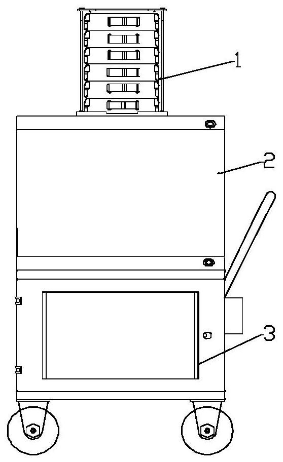
[0041] See figure 1 The present invention provides an air hot spot radiation shielding device including a shield unit 1, a lifting unit 2, and a storage unit 3; the rising unit 2 is mounted above the storage unit 3 and is welded to an integrated structure by bolts to ensure the entire device. Stab...


PUM


Abstract

The invention particularly relates to an aerial hotspot radiation shielding device which comprises a shielding unit, a lifting unit and a storage unit. The lifting unit is mounted above the storage unit through bolts and is integrally welded into an integrated structure; the shielding unit is integrally stored in the storage unit, and is taken out to be in nested connection with the lifting unit during use; and the shielding unit and the lifting unit are doubly fixed through bolts. The aerial hotspot radiation shielding device is efficient in shielding performance, convenient to disassemble and install, stable in structure and capable of being repeatedly used.

Description

technical field [0001] The invention relates to the technical field of nuclear facility radiation protection, in particular to an aerial hotspot radiation shielding device. Background technique [0002] The radioactivity of the pressurized water reactor nuclear power plant mainly comes from the active area of ​​the reactor loaded with fuel assemblies. During the operation of the nuclear power plant, the corrosion and activation products are continuously deposited on the equipment, valves, and inner walls of the main system and its auxiliary systems. A certain amount of radioactive hotspots will inevitably be formed, and the number may gradually increase. These radioactive hotspots have high radiation levels and are not easy to eliminate. They are the main reason for the increase in radiation levels in some areas or rooms in the radiation control area of ​​nuclear power plants. They not only bring about increased radiation safety risks, but also increase the collective dose o...

Claims


Application Information

Patent Timeline
IPC IPC(8): G21F5/12G21F5/14
CPCG21F5/14G21F5/12
Inventor 陈琛祥倪伟李宏强曾进忠黄刚何俊男刘杰申雁云平萍张强稂其良朱敖正和健
Owner CNNC NUCLEAR POWER OPERATION MANAGEMENT
Learn More