
Single-phase iron core reactor with uniform flux density

An iron-core reactor and magnetic density technology, applied in the direction of preventing/reducing unnecessary electric/magnetic influences, circuits, electrical components, etc., can solve problems such as high local temperature and reduced operating reliability, and achieve reduced loss and uniformity Excellent magnetic effect, eradicating the effect of overheating risk

Active Publication Date: 2022-01-21
WUJIANG TRANSFORMER
View PDF2 Cites 1 Cited by
  • Summary
  • Abstract
  • Description
  • Claims
  • Application Information

AI Technical Summary

Problems solved by technology

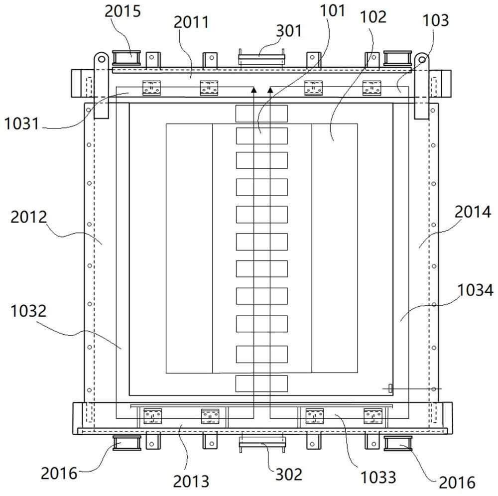
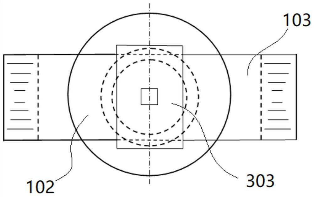
[0005] The present invention overcomes the problems of high local temperature and reduced operation reliability caused by uneven magnetic density of reactors in the prior art, and provides a single-phase core reactor with uniform magnetic density. To achieve the above-mentioned purpose, the present invention adopts The technical solution is: a single-phase iron core reactor with uniform magnetic density, including: a core assembly, a clamp assembly, and a magnetic uniform assembly. The core assembly includes an iron core column, a coil wound on the surface of the iron core column, and a The iron yoke provided inside the clip assembly, the iron yoke includes an upper yoke, a first side yoke, a lower yoke and a second side yoke connected end to end in sequence; the iron core assembly is fixed by the clip assembly, and the clip The component assembly includes an upper clamp set on the upper yoke, a first side clamp set outside the first side yoke, a lower clamp set under the lower yoke, and a side clamp set outside the second side yoke, which are connected end to end in sequence. The second side clamp; wherein, the magnetic equalization assembly includes an upper magnetic equalizer fixedly arranged on the upper clamp and a lower magnetic equalizer fixed below the lower clamp

Method used


Image

  • Single-phase iron core reactor with uniform flux density
  • Single-phase iron core reactor with uniform flux density
  • Single-phase iron core reactor with uniform flux density

Examples


Embodiment Construction

[0024] In order to more clearly understand the above objects, features and advantages of the present invention, the present invention will be further described in detail below in conjunction with the accompanying drawings and specific embodiments. structure, so it only shows the configuration related to the present invention, and it should be noted that, in the case of no conflict, the embodiments in the present application and the features in the embodiments can be combined with each other.

[0025] In the description of the present application, it should be understood that the terms "center", "longitudinal", "transverse", "upper", "lower", "front", "rear", "left", "right", " The orientation or positional relationship indicated by "vertical", "horizontal", "top", "bottom", "inner", "outer", etc. is based on the orientation or positional relationship shown in the drawings, and is only for the convenience of describing the present application and Simplified descriptions do not ...


PUM


Abstract

The invention discloses a single-phase iron core reactor with uniform flux density. The single-phase iron core reactor comprises an iron core assembly, a clamping piece assembly and a magnetism uniformizing assembly, the iron core assembly comprises an iron core column, a coil wound on the surface of the iron core column and an iron yoke arranged along the interior of the clamping piece assembly, and the iron yoke comprises an upper yoke, a first return yoke, a lower yoke and a second return yoke which are sequentially connected end to end; the iron core assembly is fixed through a clamping piece assembly, and the clamping piece assembly comprises an upper clamping piece arranged on the upper yoke, a first side clamping piece arranged on the outer side of the first side yoke, a lower clamping piece arranged below the lower yoke and a second side clamping piece arranged on the outer side of the first side yoke which are sequentially connected end to end; and the magnetism uniformizing assembly comprises an upper magnetism uniformizing piece fixedly arranged on the upper clamping piece and a lower magnetism uniformizing piece fixedly arranged on the lower clamping piece. According to the invention, a magnetism uniformizing structure is high in reliability, uniform in magnetic field, small in loss, simple in structure and process and low in cost, and magnetic lines do not transversely penetrate through the uniform magnetic silicon steel sheets.

Description

[0001] Application field [0002] The invention relates to the field of reactor manufacturing, in particular to a single-phase core reactor with uniform flux density. Background technique [0003] During the operation of iron core reactors, local overheating is very easy to occur. The main reason is that all the high-resistance main iron core circuits in operation now have the problems of uneven magnetic density and excessive magnetic density in local areas, which makes the reactor The reliability is reduced, the electromagnetic parameter waveform is distorted, the harmonic content is increased, the loss is large, and in severe cases, local overheating occurs. The reason is that the magnetic cross-section of the core column is cylindrical, and the magnetic cross-section of the iron yoke receiving its magnetic flux is rectangular, so the total magnetic density of each small rectangle of the iron yoke is different, and the total magnetic density of the middle part is much larger...

Claims


Application Information

Patent Timeline
Patent Type & Authority Applications(China)
IPC IPC(8): H01F27/34H01F27/26H01F27/245
CPCH01F27/34H01F27/263H01F27/245H01F2027/348Y02E40/30
Inventor 禹云长禹东泽
Owner WUJIANG TRANSFORMER
Learn More