Stamping device suitable for machining of different sizes and used for automobile parts

A technology of auto parts and stamping devices, which is applied in the field of auto parts processing, can solve problems such as cumbersome operation steps and automatic mold limit, and achieve the effect of improving the stability of the limit

Inactive Publication Date: 2022-01-25
任艳茹
View PDF1 Cites 0 Cited by
  • Summary
  • Abstract
  • Description
  • Claims
  • Application Information

AI Technical Summary

Problems solved by technology

[0004] This kind of stamping device clamps the mold through the threaded rod, and the threaded rod needs to be manually operated, which makes the operation steps of this kind of stamping device cumbersome, and it is impossible to use the gravity of the mold to automatically limit the mold when the mold is placed inside the stamping device

Method used


Image

  • Stamping device suitable for machining of different sizes and used for automobile parts
  • Stamping device suitable for machining of different sizes and used for automobile parts
  • Stamping device suitable for machining of different sizes and used for automobile parts

Examples


Embodiment 1

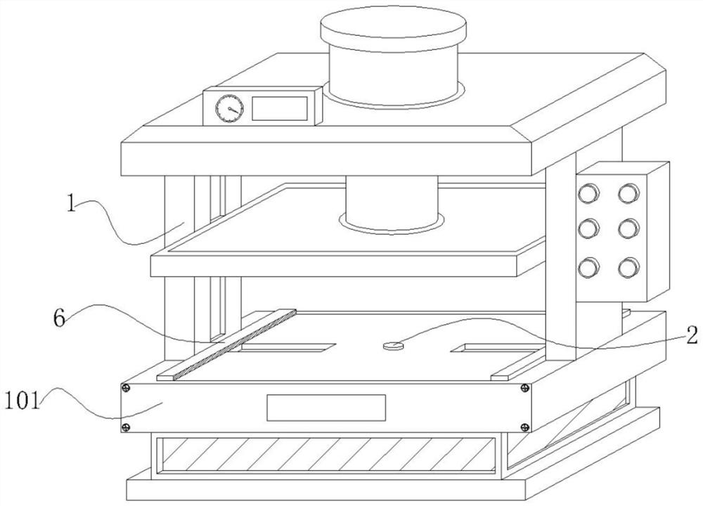
[0029] Embodiment 1: A stamping device suitable for processing auto parts of different sizes, including a stamping machine 1, a base 101 is installed on the inside of the stamping machine 1, and a transmission mechanism that can automatically limit the position is provided on the inside of the base 101;

[0030] Among them: the two sides of the upper end of the base 101 are embedded with grooves, and the transmission mechanism slides inside the groove. When the mold is placed on the inner side of the base 101, the transmission mechanism will limit the mold according to the size of the mold by using the mold pressure, which is suitable for different sizes. mold;

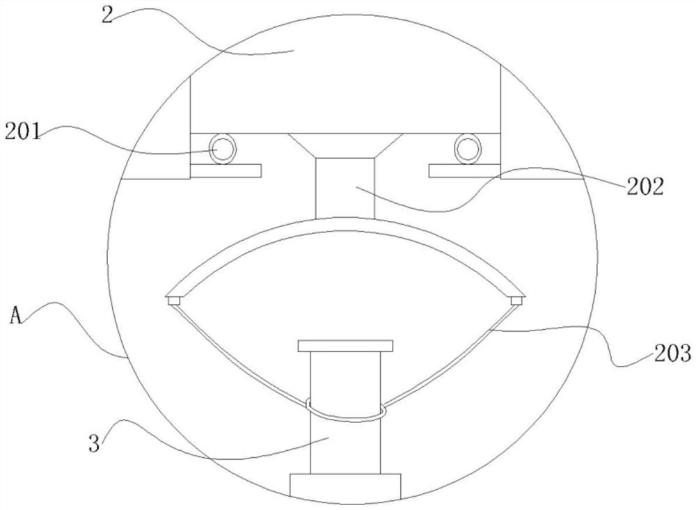
[0031] The transmission mechanism includes a briquetting block 2, a first air bag 201, a bracket 202, a stay cord 203 and a rotating shaft 3. The briquetting block 2 slides on the inside of the base 101, the first air bag 201 expands and contracts on both sides of the lower end of the briquetting block 2, and the brack...

Embodiment 2

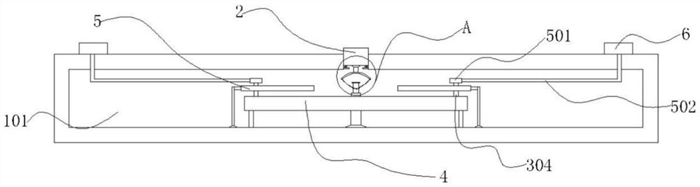
[0039] Embodiment 2: with reference to instruction manual Figure 4 and 5 It can be seen that the difference between Embodiment 2 and Embodiment 1 is that the transmission mechanism includes a bearing 301, a connecting rod 302, a gear 303, a snap ring 304, a circular ring 4, a tooth piece 401, a track 5, a collar 501, and a connecting frame 502 and the second air bag 6, the bearing 301 is installed on the outside of the rotating shaft 3, the connecting rod 302 and the gear 303 rotate on one side of the bearing 301 in turn, the snap ring 304 rotates on one side of the gear 303, and the ring 4 and the gear piece 401 rotate and insert Fitting on the outside of the gear 303, the track 5 is fixed inside the base 101, the collar 501 slides on the outside of the snap ring 304, and the connecting frame 502 and the second airbag 6 are installed on one side of the collar 501 in turn;

[0040] The snap ring 304 slides through the rail 5 and the inner side of the collar 501 in turn, the ...

Embodiment 3

[0047] Embodiment 3: with reference to instruction manual Figure 6 It can be seen that the difference between Embodiment 3 and Embodiments 1 and 2 is that the two sides of the second airbag 6 are inlaid with bumps 601, the back of the second airbag 6 is penetrated with a negative pressure valve 602 installed, and the front of the second airbag 6 Mosaic limited layer 603;

[0048] The thickness of the limiting layer 603 is 1-2 cm less than the second airbag 6 as a whole, and one side of the limiting layer 603 is attached to the second airbag 6;

[0049] Wherein: when the second airbag 6 is extruded to both sides of the mold according to the second embodiment, the bump 601 is depressed to the inside of the second airbag 6 by the extrusion of the mold, and the negative pressure valve 602 is used to form a negative pressure state inside the second airbag 6 , and furthermore, the limit layer 603 is deformed as a whole, and the limit layer 603 is concave, so as to assist the secon...


PUM


Abstract

The invention provides a stamping device suitable for machining of different sizes and used for automobile parts. A base is installed on the inner side of a stamping machine, a transmission mechanism capable of achieving automatic limiting is arranged on the inner side of the base, the transmission mechanism comprises a pressing block, first air bags, a support, a pull rope and a rotating shaft, the pressing block slides on the inner side of the base, the first air bags stretch out and draw back on the two sides of the lower end of the pressing block, the support slides at the lower end of the pressing block, the pull rope rotates on the two sides of the lower end of the support, the rotating shaft rotates on the inner side of the pull rope, the first air bags are arranged in an oval shape, and the height of the first air bags is 4-10 cm. A bearing sequentially drives a connecting rod to swing, so that a gear and a tooth piece are rotationally embedded, and the gear drives a clamping ring to swing at the same time; under limitation by a track, the clamping ring can drive a lantern ring to slide horizontally, so that the lantern ring can drive second air bags to slide horizontally through a connecting frame, the second air bags can limit the two sides of a die after sliding, and the stamping device can limit the die according to the size of the die.

Description

technical field [0001] The invention relates to the technical field of auto parts processing, in particular to a stamping device for auto parts suitable for processing different sizes. Background technique [0002] The stamping device is a press machine, which is used to stamp and form auto parts of different sizes. Since the stamping device is a fixed part as a whole, and the sizes of auto parts are different, the stamping device cannot be limited according to the size of the auto parts; [0003] In view of the technical problems of the stamping device mentioned above, after searching, it was found that there is a patent No. CN201910791978.7, a stamping device suitable for processing automobile parts of different sizes, which is suitable for processing automobiles of different sizes The stamping device for parts uses the threaded rod to drive the first clamping plate and the clamping device to clamp the lower mold, which is suitable for stamping devices for auto parts proce...

Claims


Application Information

Patent Timeline
IPC IPC(8): B21D22/02B21D37/14
CPCB21D22/02B21D37/14
Inventor 任艳茹
Owner 任艳茹
Why Eureka
Try Eureka