Expansion valve

A technology of expansion valve and defrost valve, applied in the field of expansion valve, can solve the problem of high manufacturing cost, and achieve the effects of reducing pressure relief, reducing manufacturing cost and increasing moving speed

Pending Publication Date: 2022-01-25
WENLING HENGFA AIRCONDITION COMPONENTS
View PDF2 Cites 3 Cited by
  • Summary
  • Abstract
  • Description
  • Claims
  • Application Information

AI Technical Summary

Problems solved by technology

[0005] The purpose of the present invention is to solve the above-mentioned problems in the existing technology, and propose an expansion valve to solve the problem of high manufacturing cost after the defrosting function is added to the existing expansion valve

Method used


Image

  • Expansion valve
  • Expansion valve
  • Expansion valve

Examples


Embodiment 1

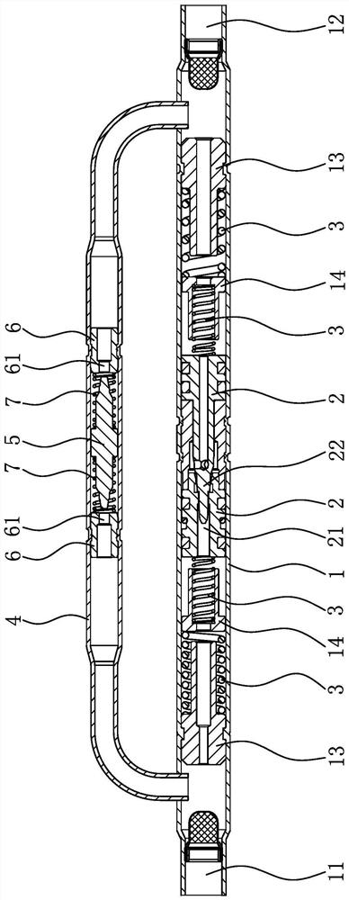
[0046] Such as figure 1 As shown, an expansion valve includes a main valve body 1 and a defrosting valve body 4. Both the main valve body 1 and the defrosting valve body 4 are tubular. One end of the main valve body 1 is a cooling inlet 11, and the other end is a heating inlet. The inlet 12 and the two ends of the main valve body 1 are fixed with limit sleeves 13, and two main valve cores 2 capable of sliding are arranged between the two limit sleeves 13, and the gap between the main valve core 2 and the limit sleeve 13 A spring seat 14 is arranged between, a main spring 3 is arranged between the spool and the spring seat 14, a main spring 3 is also arranged between the spring seat 14 and the limit sleeve 13, and a joint is opened on one of the main spool 2. Orifice 21, the other main valve core 2 has a columnar plug joint 22 on the end surface. A throttling channel is formed between them, and in the process of cooling or heating, the pressure difference between the two ends ...

Embodiment 2

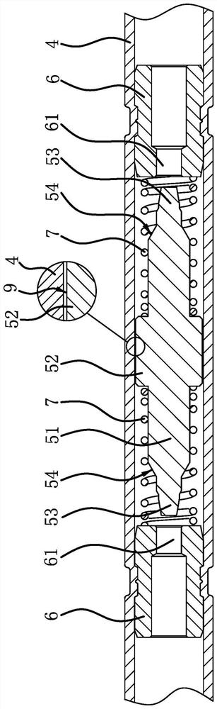
[0052] The structure of the expansion valve is basically the same as that of Embodiment 1, the difference is that Figure 4 , Figure 5 , Figure 6As shown, the defrosting valve body 4 is also provided with a spacer 8 along the length direction. The spacer 8 is made of steel sleeves. The flow hole 61 communicates with the inner hole of the spacer 8. The outer diameter of the spacer 8 is smaller than the inner diameter of the defrosting valve body 4. The spacer 8 and the defrosting valve body 4 are coaxially arranged so that the outer peripheral surface of the spacer 8 is in contact with the defrosting valve body. A return channel 9 is formed between the inner peripheral surfaces of the body 4 , the defrosting valve core 5 is arranged in the spacer 8 , and the outer peripheral surface of the guide part 52 is slidingly fitted with the inner peripheral surface of the spacer 8 . The spacer 8 is provided with two return ports 81 along the length direction, the return ports 81 com...

Embodiment 3

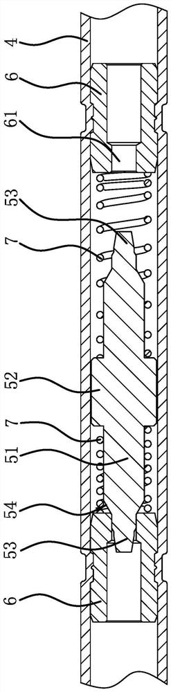
[0054] The structure of the expansion valve is basically the same as that of Embodiment 1, the difference is that Figure 7 , head 8, Figure 9 As shown, the defrosting valve body 4 is also provided with a spacer 8 along the length direction. The spacer 8 is made of steel sleeves. The orifice 61 communicates with the inner hole of the spacer 8, the outer peripheral surface of the spacer 8 fits the inner peripheral surface of the defrosting valve body 4, the defrosting valve core 5 is arranged in the spacer 8, and the outer peripheral surface of the guide part 52 is in contact with the spacer 8, the inner peripheral surface is slidingly fitted, and the axial middle part of the spacer 8 is provided with a strip-shaped return port 81 in the axial direction. The axial length of the return port 81 is greater than the axial length of the guide part 52. Under the action of the guide part 52 is located in the middle of the return port 81, the width of the two ends of the return port ...


PUM


Abstract

The invention provides an expansion valve, and belongs to the technical field of air conditioner parts. The expansion valve solves the problem that an existing expansion valve is high in manufacturing cost after a defrosting function is added is solved. The expansion valve comprises a main valve body and a defrosting valve body, wherein the two end ports of the defrosting valve body are both communicated with the main valve body, a valve element assembly is arranged at the position, between the two end ports of the defrosting valve body, in the main valve body, two limiting parts are arranged in the defrosting valve body, and the two limiting parts are both provided with overflowing holes which are formed in the length direction of the defrosting valve body in a penetrating manner. A defrosting valve element capable of sliding and blocking the overflowing holes is arranged between the two limiting parts, auxiliary springs are arranged between the defrosting valve element and the two limiting parts, the defrosting valve element can be separated from the two limiting parts under the action of auxiliary springs, and the starting elastic force value of the main spring is larger than the elastic force value generated when the auxiliary springs are compressed till the defrosting valve element blocks the overflowing hole. According to the expansion valve, after the defrosting function is added to the expansion valve, the manufacturing cost is low.

Description

technical field [0001] The invention belongs to the technical field of air-conditioning components and relates to an expansion valve. Background technique [0002] The compressor, condenser, expansion valve, and evaporator constitute the refrigeration system. The expansion valve is an important part of the refrigeration system. It is generally installed between the condenser and the evaporator. The expansion valve can make the evaporator evaporate The gas is pressurized by the compressor and liquefied to a high-temperature and high-pressure liquid refrigerant, and throttled through its orifice to become a low-temperature and low-pressure mist liquid refrigerant, and then the refrigerant absorbs heat in the evaporator to achieve the cooling effect. [0003] For example, the expansion valve disclosed in the patent application (application number: 201711366377.9) includes a valve core one and a columnar valve core two. The outer diameter of the plug joint is smaller than the o...

Claims


Application Information

Patent Timeline
Patent Type & Authority Applications(China)
IPC IPC(8): F16K1/38F16K1/42F16K1/32F16K27/02
CPCF16K1/38F16K1/42F16K1/32F16K27/0254
Inventor 金耿王兴会毛青峰
Owner WENLING HENGFA AIRCONDITION COMPONENTS
Why Eureka
Try Eureka