[0027] The invention will be described in detail below with reference to the specific embodiments shown in the drawings. However, these embodiments do not limit the invention, and those skilled in the art are included in the scope of the invention in accordance with the structures, methods, or functional transformations of the present invention in accordance with these embodiments.
[0028] It should be understood that, for example, "upper", "above", "lower", "lower", "lower", and "upper", ",", "the term", "," The relationship between another unit or feature. The term space relative position can be intended to include different orientations other than the orientation shown in the drawings in use or operation.
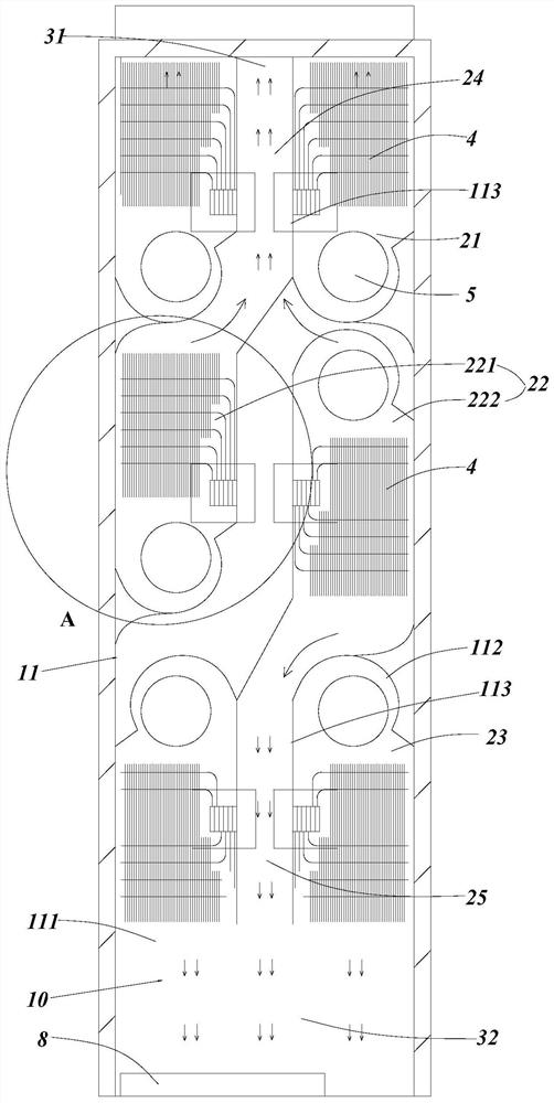
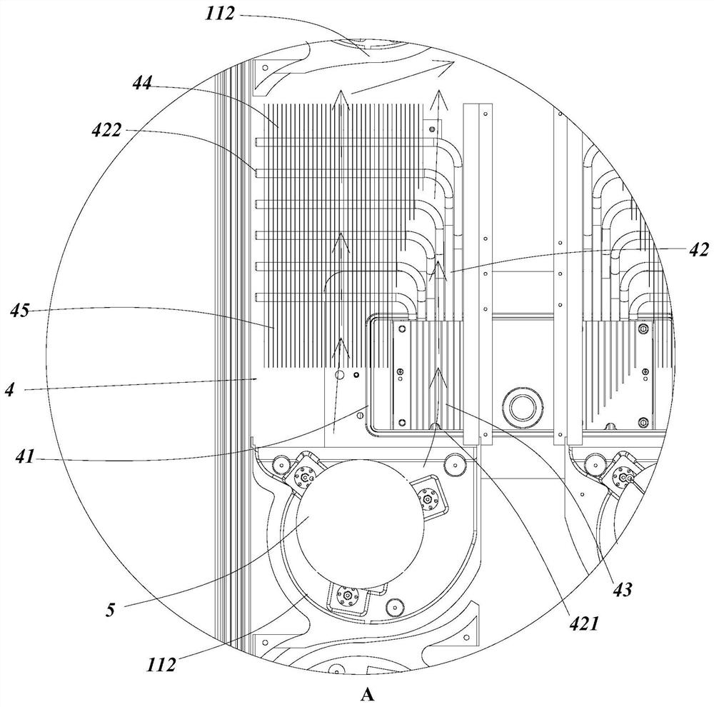
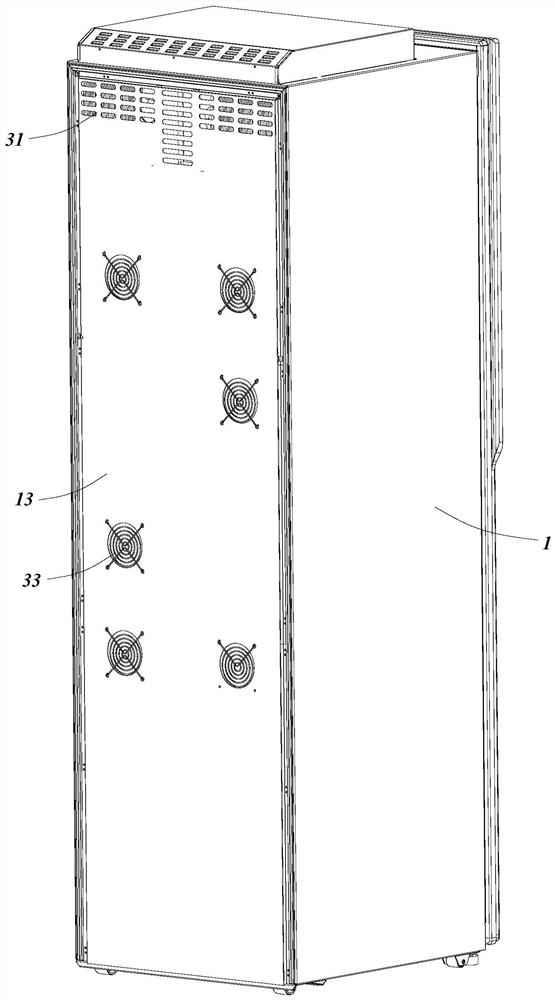
[0029] An embodiment of the present invention provides a wine cabinet with a refrigeration assembly for refrigerating a refrigeration, and a heat dissipation device that is uniformly refined in the wine cabinet, the heat dissipation device being dispersed At the same time, it is also avoided that the calorificed heat is again inhaled, with a good refrigeration and heat dissipation.
[0030] Specifically, the wine cabinet introduced in this example includes the box 1 and the door body 9, and the box body 1 and the door body 9 are surrounded by the refrigemberdrost room, and the cooling room is placed, the refrigeration assembly is cooled to the refrigeration room. The heat sink is provided in the outer side of the refrigeration room for removing the heat generated when the refrigeration assembly is refrigerated.
[0031] In this embodiment, the bottom surface of the wine cabinet is horizontal, the wine cabinet is above the direction of the horizontal plane, and the reverse direction is defined as below, and the upper downward direction can also be defined as the height direction of the wine cabinet. The definition door 9 is rearward with respect to the direction of the casing 1, and the rear backing plate 13 is rearward relative to the direction of the casing 1. by figure 1 The direction of the rear view refrigeration interior side is an example, the view is the forward direction, in order to facilitate the description of the heat sink, on the horizontal plane, the wine cabinet is defined vertically with the front-rear direction. For the left and right directions. The horizontal plane is only a name definition, and is not limited to a "level" in the sense of physical schematic; of course, in the preferred embodiment, the high direction and physical direction of the wine cabinet (also reference The gravity direction is parallel, and the horizontal plane is correspondingly parallel to the horizontal plane in the physics.
[0032] The heat dissipation device of the present embodiment is disposed behind the wine cabinet, and the refrigeration assembly is disposed in the inner portion of the refrigeration chamber toward the door 9, the cabinet 1 includes a heat sink 11 and a refrigeration case 121, The backplane 13 is provided in the heat sink 11 and the heat-dissipating heat chamber 10 is coiled therewith, and the air-hole cover 14 is provided to the refrigerator 121 and the cooling chamber 20 is incorporated therewith.
[0033] Cooling device Figure 1 ~ 3 As shown, the heat dissipation chamber 10 is disposed on the rear side of the refrigeration chamber, the rear back plate 13 is a plate of the back of the wine cabinet, and the heat dissipation chamber 10 is provided by the air opening and air opening of the heat sink 11 and / or the rear back plate 13. Connect with the outside, the heat dissipation device can feed from the top, or the operation of intake and exhaust from the position of the rear back plate 13, the heat dissipating device inhales into the outside, through the heat dissipation chamber 10, The internal generated heat is blown up with air, and heats the heat taken away to heat dissipation.
[0034] like figure 1 and figure 2 As shown, the heat dissipation chamber 10 includes a heat dissipation auxiliary chamber, and the first heat dissipation chamber 21, the second heat dissipation chamber 22, and the third heat dissipation chamber 23, the first heat dissipation chamber 21, the second heat dissipation chamber 22. And the third heat dissipation chamber 23 is formed in the height direction of the heat sink 11, since the wine cabinet has the highest height in the vertical direction, these flap limits the internal gas in the direction of the height. The exhaust is made reasonable and compact inner space layout, and the heat dissipation effect is good. The first heat dissipation chamber 21 of the present embodiment is disposed above the second heat dissipation chamber 22, and the second heat dissipation chamber 22 of the present embodiment is disposed above the third heat dissipation chamber 23. That is, the first heat dissipation chamber 21 is disposed at most, and the third heat dissipation chamber 23 is disposed at the bottom, and the second heat dissipation chamber 22 is disposed in the middle.
[0035] The first heat dissipation chamber 21, the second heat dissipation chamber 22, and the third heat dissipation chamber 23 are arranged in parallel, the heat dissipating covalent cavity includes a first heat dissipation auxiliary cavity 24 disposed between the two sets of first heat dissipation cavities, and is disposed The second heat dissipation auxiliary cavity 25 between the two sets of third heat dissipation cavities 23.
[0036] The air outlet includes simultaneously connecting the first exhaust port 31 of the first heat dissipation chamber 21 and the first heat dissipation covalent cavity 24, and the second air outlet 32 of the third heat dissipation chamber 23 and the second heat dissipation cavity 25, the first air exit 31 and the heat dissipation air port 33 of the first heat dissipation chamber 21 is located at both ends of the first heat dissipation chamber 21, and the heat dissipation air inlet 33 of the second air outlet 32 and the third heat dissipation chamber 23 is located at the third heat dissipation chamber 23. At both ends of the height direction, the second heat dissipation chamber 22 includes a left radiation chamber 221 and a right heat dissipation chamber 222, the left radiation chamber 221 and the right heat dissipation cavity 222 thereon, and the second heat-dissipating auxiliary cavity 24 Cavity 25.
[0037]The heat dissipation air inlet 33 of the first heat dissipation chamber 21 is respectively disposed on both ends of the first heat dissipation chamber 21, that is, the two have a certain distance, so the airflow blown from the first air outlet 31 is again Inside the first heat dissipation chamber 21, the heat gantry blown from the second exhaust cartridge 32 will not be bracked, the heat dissipation device avoids a lot of hot air flow. The problem of absorbing the heat dissipation space increases heat dissipation efficiency, further improves the cooling effect of the wine cabinet.
[0038] The left and right of this embodiment is only example, figure 1 The left radiation chamber 221 is connected to the first heat dissipation covalent cavity 24, or the right heat dissipation chamber 222 is connected to the first heat dissipation covalent cavity 24, and the second heat dissipation chamber 22 on the other side is similar. Thus, the hot gas in the two second heat dissipation cavity 22 in the intermediate position is discharged from the upper and lower ends, and the heat gas shunt effect is good, and the heat dissipation efficiency is improved.
[0039] The first air outlet 31 of the present embodiment is disposed at the top of the wine cabinet, further first air port 31 can be simultaneously disposed above the top and the rear back plate 13 of the heat sink 11, such as figure 1 and image 3 As shown, the top is also provided with a circuit board such that the blown air flow can blow the heat generated by the circuit board, and generally from the hot air flow temperature blown from the first air outlet 31 is generally lower than the temperature of the circuit board, it is achieved in blowing hot air At the same time, the effect of cooling the circuit board; the second air port 32 is disposed below the heat dissipation chamber 10 and the evaporating dishes 8, the evaporating dish of the heat dissipation chamber 10, the evaporating dish 8 uncoated, the third outlet blown out The heat gas accelerates the moisture evaporation in the condensed water.
[0040] Further, the heat sink further includes a heat dissipation fan 5, a heat dissipation fan 5 includes a first heat dissipation fan 5, a second heat dissipation fan 5, and a third heat-dissipating fan 5, one end of the first heat dissipation chamber 21 in the wind turret, a first heat dissipation fan 5 On the other end, the first air port 31 is connected, and one end of the second heat dissipation chamber 22 has a second heat dissipation fan 5. The other end is connected to the heat-fixing cavity, and the third heat dissipation chamber 23 ends of the wind channel takes a third heat dissipation Fan 5, the other end connects the second outlet 32. The cooling fan 5 provides power for the flow of the airflow.
[0041] Further, the baffle 113 and the heat dissipation stopper 112 provided between the rear back plate 13 and the heat dissipation case 11, the heat dissipation back plate 111, the heat sink 113, the heat dissipation volute 112, and the rear back plate 13 There is a radiating chamber 10 between 13, and the rear back plate 13 is provided at the heat-dissipating volute 112, and the heat dissipation fan 5 is provided in the heat dissipation volute 112. The first heat dissipation chamber 21, the second heat dissipation chamber 22, and the third heat dissipation chamber 23 are disposed, and the first heat-dissipating fan 5, the second heat sink 5, and the third heat dissipation fan 5 are provided in the heat dissipation volute 112. And the first heat dissipation fan 5 and the second heat dissipation fan 5 and the third heat-dissipating fan 5 are provided as a centrifuge fan, and the outer air is inserted from the end face of the heat dissipation volute 112, and then blow to the circumferential surface of the volute.
[0042] The heat-dissipating chamber 10 and the bottom surface of the refrigeration chamber 20 are formed between the cooling bottom plate 121 of the refrigerator 121, respectively, and the heat dissipation pad 111 and the cooling bottom plate 121 can be provided. Foaming formed insulation filler.
[0043] Further, the direction of the second heat dissipation chamber 22 faces the curved sidewall of the heat dissipation volute 112, and is connected to the heat dissipation mechanism along the arc-shaped side wall. The heat-dissipating chamber 22 is provided with respect to the heat dissipation cavity 21 toward the first heat dissipation chamber 21, and when the air flow within the second heat dissipation chamber 22 is blown upward, until it is blown to the first heat dissipation chamber 21 The heat dissipation volute 112, the outer surface of the heat dissipation volute 112 is a circular arc shape, and when the air flow is blown to the heat dissipation volute, the heat dissipation volute 112 flows toward the heat dissipation supplemental cavity, that is, the heat dissipation of the first heat dissipation chamber 21 112 The airflow surface of the second heat dissipation chamber 22 is formed, and the smooth movement of the airflow is better guided by the shape of the volute.
[0044] Further, such as figure 1 As shown, the left radiation chamber 221 is connected to the baffle 113 of the first heat dissipation chamber 21 on the right, the heat dissipation air port 33, the left radiation chamber 221, the first heat dissipation cavity 24, and the first air outlet 31 form airflow channel 120; The right heat dissipation chamber 222 connects the baffle 113 of the third heat dissipation chamber 23 on the left side, the heat-dissipating air port 33, the right heat dissipation chamber 222, the second heat dissipation cavity 25, and the second air outlet 32 form airflow channel 120. That is, the gas stream of the left radiative chamber 221 does not enter the right heat dissipation chamber 10, the truth is the same, and the second heat dissipation chamber 22 on both sides is independently opened.
[0045] Further, a heat radiating unit provided in the heat dissipation chamber 10, the heat dissipation unit includes a plurality of vertically disposed parallel fins, and the fin limits the airway of the heat dissipation chamber 10.
[0046] And, the heat radiating unit further includes a heat sink 41, a heat dissipation tube 42, a first heat sink 43, and a second heat sink portion 44, a heat sink 41, and a heat sink 43, and a second heat sink 44, both including fins, heat dissipation. The tube 42 includes a heat sink 421 and a heat dissipation end 422 that is sandwiched between the heat sink 41 and the first heat sink 43, and the heat dissipation end 422 passes through the wings of the plurality of second heat sink 44. The wine cabinet includes a semiconductor refrigeration unit 6, and the heat end of the semiconductor refrigeration unit 6 is a heat generating apparatus connected to the heat sink 41, that is, the heat sink 41 is bonded to the heat end of the semiconductor refrigeration unit 6, and the heat is received, and the heat is heat The tube 42 is transmitted to the second heat sink portion 44, and the fins of the first heat sink portion 43 are also used for heat dissipation, the gap between the adjacent first heat dissipation portions 43 and the fins of the second heat sink 44 guide the airflow. In the flow direction, the fin is displaced in the height direction of the wine cabinet, so that the hot air flow flows up and down along the first heat dissipation chamber 21 or the second heat dissipation chamber 22.
[0047] The heat dissipation pipe 42 is filled with deionized water as a medium transmitted, and a sintered tube is used.
[0048] Further, the air outlet includes a third outlet of the rear back plate 13, the third outlet discharge position is disposed in the connection position of the second heat dissipation chamber 22 and the heat dissipation covalent cavity, so that the hot gas within the second heat dissipation chamber 22 is from the first The air outlet 31 and the second air outlet 32 blow out, a portion blows from the third outlet, since the first air head 31 and the second air outlet 32 flow out part of the air flow, the amount of gas flow blowing out of the third outlet is reduced, and The thermal air of the heat dissipation fan 5 is very hot.
[0049] This example also discloses a refrigeration assembly, such as Figure 4 and Figure 5 As shown, including the air duct cover 14, the refrigerator 121 and the air duct cover 14 are incorporated by the surface of the cooling chamber 20, the surface of the air duct cover 14 and a plurality of refrigerated air outlet 35; the air duct cover 14 The rear is the cooling chamber 20, the front side is the refrigember room, and the cooling air inlet 34 is sucked into the airflow in the refrigeration chamber, and then the cooling chamber 20 is refrigerated, and then the refrigeration outlet 35 is blown back to the refrigeration room. A plurality of refrigerated air outlets 35 are uniformly disposed on the surface of the air duct cover 14.
[0050] The refrigeration assembly also includes a plurality of air wind turbies 122, a cooling fan 7, and a refrigeration unit 6, and the air-winding plate 122 is compared with the refrigeration case 121 and the air-stop cover 14, adjacent two air-mold 122, refrigerator 121 The airflow passage 120 in which communication is formed between the air outlet 35, and the cooling fan 7 is disposed in the cooling chamber 20, and the airflow side of the cooling fan 7 communicates with the wind turbine 120, and the refrigeration unit 6 includes a refrigerator 61 and The refrigerator 61 connected to each other is connected to each other, and the refrigerator 61 is connected to the refrigeration apparatus, and the cooling fin 62 is opposed to the air-hole cover 14, and in one end of the extension direction of the cooling fin 62, the cooling air port 34 is connected. One end is provided on the wind side of the cooling fan 7.
[0051] The gas is entered into the refrigeration chamber 20 from the refrigerating air inlet 34 on the air duct cover 14, and then passes through the plurality of refrigeration fins 62, and then enters the wind side of the cooling fan 7 after heat transfer, through the wind side of the cooling fan 7. Blowing to the airflow channel 120, eventually blown out from a plurality of refrigerated air outlets 35, forming uniform refrigeration in the entire chamber. The cooling fins 62 simultaneously acts as a uniform refrigeration and guiding the flow of airflow flow.
[0052] like Figure 5 As shown, the refrigerator 121 is provided toward the direction of the airway cover 14, and the groove 1211 and the refrigerator 7 are in the wind chamber, and the refrigerator side of the cooling fan is toward the wind chamber, the air cavity has The opening 1212 toward the airflow fin 62, the opening 1212 limits the direction of the flow of airflow flows, and the gas stream into the cooling fan 7 does not return into the groove 1211, and can only be blown out from the airflow channel 120.
[0053] Further, the refrigerating air port 34 is provided at the bottom of the air duct cover 14, and the refrigeration unit 6 is disposed below the cooling fan 7, and the refrigeration air outlet 35 is disposed above the cooling air outlet 34, and the gas having a lower temperature has downwards. The trend of exercise, so the cooling outlet 35 is placed above, so that the wind is naturally settled below, which is conducive to the cycle of the internal air condition.
[0054] The refrigerator 7 of the present embodiment is provided as a centrifuge fan, and the air-winding plate 122 is disposed along the circumferential direction of the center of the blower, and the direction of the incoming air flow is vertical in the direction of the blown air flow, and it is convenient to blow the air in the direction of the circumference, the air supply area is larger. It is conducive to evenly airborne.
[0055] Further, the plurality of air strip 122 are arranged in parallel to the circumferential direction of the air-duct cover 14, and the gas stream blown from the centrifuge fan has a tangential speed, and the blown air flow is blown out in a spiral shape, which is advantageous to blow it. To farther position, it is conducive to airborne air in a further position.
[0056] Further, the refrigeration unit 6 further includes a cooling tube 63, and the cooling tube 63 is connected to the refrigerator 61, and the other end passes through several refrigerant fins 62, and the refrigerator 63 of the present embodiment is filled with the R1233ZD refrigerant as a refrigerant. It is a sintered tube. The cold amount of the refrigerator 61 is transmitted to the cooling fin 62 by the cooling pipe 63 to achieve more efficient delivery of the cold amount.
[0057] And, the extended direction of the cooling fin 62 is disposed in the vertical direction, and the cooling tube 63 passes through the refrigerator 61 in the horizontal direction, so that the cooling gas is inhaled from the bottom of the bottom, move vertically to the groove 1211. The position is short and sufficiently in contact with the cooling fin 62 in its internal motion.
[0058] Further, the refrigerator 121 is provided in the cooling case, and the refrigerator is disposed as a semiconductor refrigeration apparatus, and the refrigerator 61 and the semiconductor refrigeration apparatus are opposed to the other side of the semiconductor refrigeration apparatus and the heating unit 4 described above.
[0059] Further, the refrigerating air inlet 35 includes an upper air outlet 351 and a side outlet air outlet 352, and the upper outlet air port 351 is disposed above the cooling fan 7, and the side outlet air port 352 is disposed on the left and right sides of the cooling fan 7, thereby achieving from above and The winding wind in the two sides, so that the internal air air flow is more uniform.
[0060] Compared with the prior art, the present embodiment has the following beneficial effects:
[0061] (1) The heat gant flow inside the second heat dissipation chamber 22 on the left and right side is discharged along the first heat dissipation covalent cavity 24 and the second heat dissipation covalent cavity 25. The heat dissipation air inlet 33 of the third radiating chamber 23 is achieved, and the effect of heat gas discharged from the heat dissipation chamber 10 is no longer inhaled by the other heat dissipation chambers 10, and the hot gas within the two second heat dissipation cavity 22 in the intermediate position is from The upper and lower ends are discharged, the hot air split effect is good, improved heat dissipation efficiency, and further improve the cooling effect of the wine cabinet.
[0062](2) After the refrigeration unit 6 acquires the cold amount, the cold amount is transferred to the fins, and the adjacent refrigeration fins 62 form a steady-air flow direction between the wind turbine 14, the gas from the airway The refrigerating air inlet 34 on the cover plate 14 enters the refrigeration chamber 20, and then passes through the plurality of refrigerated fins 62, after the heat transfer, the heat transfer, the wind side of the refrigerator 7, by the winding fan 7 blows to the airflow channel. 120, finally blown out from a plurality of refrigerated air outlets 35, forming uniform refrigeration in the entire room.
[0063] It should be understood that although this specification describes in accordance with an embodiment, it is not to include only one independent technical solution. This narrative method of the specification is simply, and those skilled in the art will use the specification as a whole, each The technical solution in the embodiment can also be combined, and other embodiments which will be appreciated by those skilled in the art can also be combined.
[0064] A series of detailed descriptions listed above are intended to be specifically described in the feasibility embodiments of the invention, which are not intended to limit the scope of the invention, and any equivalent embodiments that are not separated from the spiritual spirit of the present invention or Changes should be included within the scope of the invention.