
Remote multi-site simultaneous test method for testing environment test equipment

A technology for environmental testing and testing methods, which is applied to measuring devices, structural details of gas analyzers, instruments, etc., can solve problems such as high testing costs, high work intensity, and insufficient professional testing personnel, and achieve social benefits. Beneficial and economical Effects of travel costs and time, improved normative and data validity

Pending Publication Date: 2022-01-25
广州市圣高测控科技有限公司
View PDF5 Cites 0 Cited by
  • Summary
  • Abstract
  • Description
  • Claims
  • Application Information

AI Technical Summary

Problems solved by technology

[0006] Aiming at the deficiencies of the prior art, the present invention provides a remote multi-site simultaneous test method for testing environmental test equipment, which solves the problems of low efficiency of on-site detection, measurement and calibration, high work intensity, insufficient professional testing personnel team, and cross-provincial field The long distance of detection leads to high detection cost and low efficiency

Method used


Image

  • Remote multi-site simultaneous test method for testing environment test equipment
  • Remote multi-site simultaneous test method for testing environment test equipment
  • Remote multi-site simultaneous test method for testing environment test equipment

Examples


Embodiment Construction

[0033] The following will clearly and completely describe the technical solutions in the embodiments of the present invention with reference to the accompanying drawings in the embodiments of the present invention. Obviously, the described embodiments are only some, not all, embodiments of the present invention. Based on the embodiments of the present invention, all other embodiments obtained by persons of ordinary skill in the art without making creative efforts belong to the protection scope of the present invention.

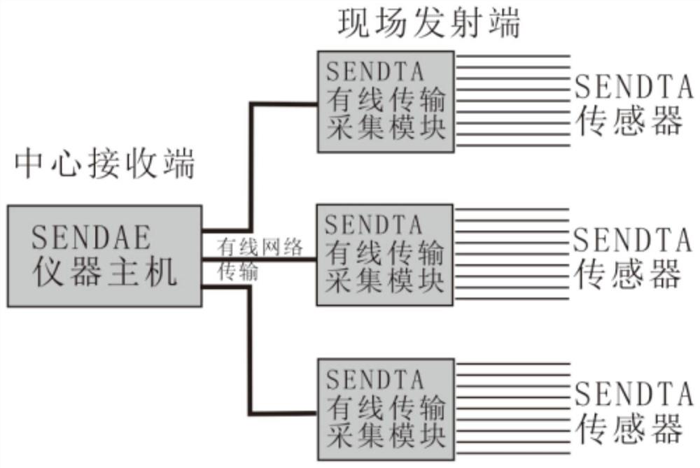
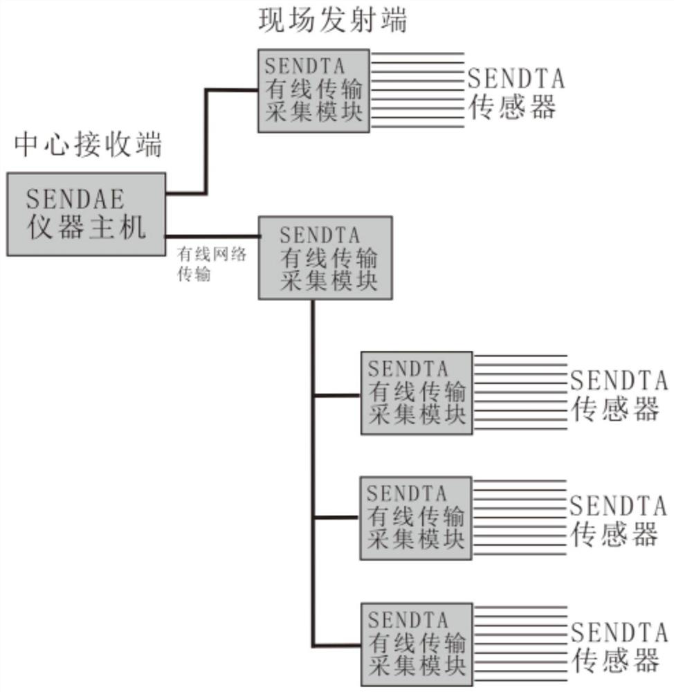
[0034] see Figure 1-6 , the embodiment of the present invention provides a technical solution: a remote multi-site simultaneous testing method for testing environmental testing equipment (sites), and the method is also suitable for proficiency testing agencies to test the temperature, humidity, For the capability verification of parameters such as wind speed and pressure, the inspection and testing laboratory conducts monitoring and measurement of parameters ...


PUM


Abstract

The invention discloses a remote multi-site simultaneous testing method for testing environment test equipment. The method comprises the following steps: S1, writing national metering detection regulation requirements into an instrument host program; S2, arranging an acquisition transmitting module and a sensor; S3, sending the data; S4, acquiring a detection calibration report; and S5, outputting the original data document; The invention relates to the technical field of equipment testing. According to the remote multi-site simultaneous testing method for testing the environment test equipment, a remote detection mode is used for replacing an existing scattered person door-to-door detection mode, and the remote multi-site simultaneous testing method is characterized in that an instrument host (a detection and analysis end) is placed in a metering center body, and an acquisition and emission module (an acquisition and emission data module) is placed in a detected equipment site; and the instrument hostand the acquisition and transmission module transmit and receive in a remote data transmission mode and are not limited by distance, so that the acquisition and transmission module can be transmitted to a detection site, measurement and detection personnel do not need to arrive at the site, and the travel expense and time are greatly saved.

Description

technical field [0001] The invention relates to the technical field of equipment testing, in particular to a remote multi-site simultaneous testing method for testing environmental testing equipment. Background technique [0002] At present, China's metrology institutes at all levels (third-party certification and testing institutions) take the inspection of environmental test equipment as an example. Most of them require metrology inspectors to come to the door with standard testing equipment (to the site where the tested equipment is used) for testing and calibration. The reason is that most Environmental test equipment is large-scale and heavy production equipment. It is inconvenient to send the tested equipment to the metrology institute for test calibration. The metrology center does not have enough space to receive large-scale tested equipment and a large number of tested equipment. The environmental test equipment must be installed and debugged in the actual operation...

Claims


Application Information

Patent Timeline
Patent Type & Authority Applications(China)
IPC IPC(8): G01N33/00G01D21/02G08C17/02
CPCG01N33/007G01N33/0006G01D21/02H04L67/025H04L67/1095H04L67/12G08C17/02
Inventor 陈俞龙邓雪勇
Owner 广州市圣高测控科技有限公司
Learn More