Supercharge Your Innovation With Domain-Expert AI Agents!

Pressure-varying air-exhausting duct structure

An air exhaust duct and pressure-transforming technology, which is applied to vertical pipes, building components, building structures, etc., can solve the problems of inconvenient installation of pressure-transforming components, positioning and installation troubles, and achieve low production costs and convenient installation. The effect of installation and easy placement

Inactive Publication Date: 2004-02-25
林润泉
View PDF1 Cites 0 Cited by
  • Summary
  • Abstract
  • Description
  • Claims
  • Application Information

AI Technical Summary

Problems solved by technology

Since the two sides of the transformer part are tightly pressed against the inner wall of the main pipe, this brings troubles to its placement and installation. Installation of pressing parts

Method used


Image

  • Pressure-varying air-exhausting duct structure
  • Pressure-varying air-exhausting duct structure
  • Pressure-varying air-exhausting duct structure

Examples


Embodiment Construction

[0023] The present invention will be further described below in conjunction with the accompanying drawings.

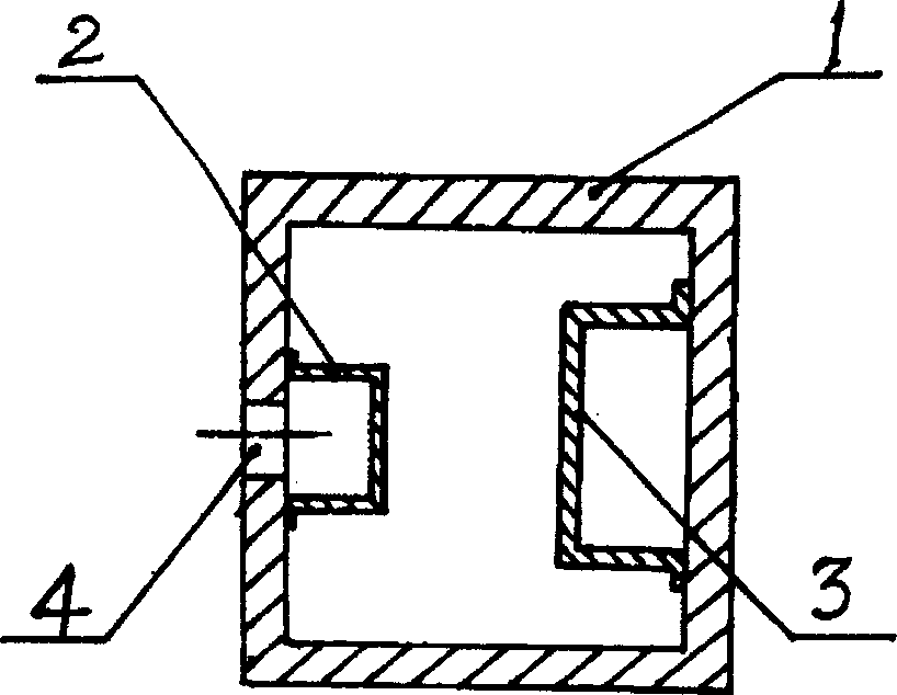
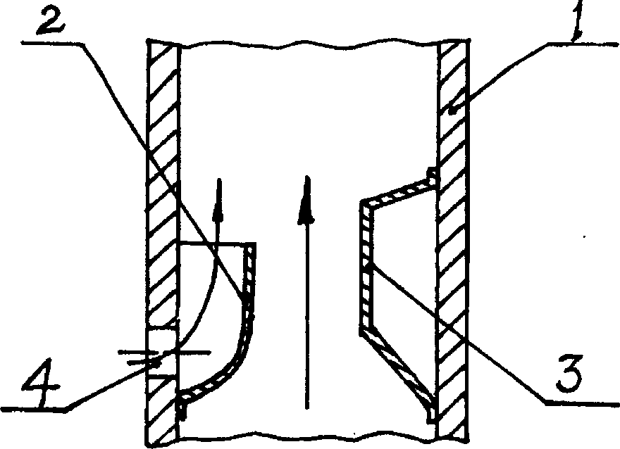
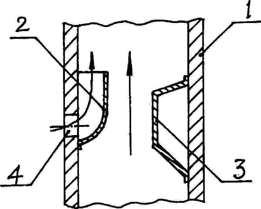
[0024] exist figure 1 The schematic diagram shown and figure 2 , image 3 , Figure 4 In the schematic diagram shown, the present invention is composed of a gas discharge pipe 1 provided with an air inlet 4, an exhaust guide pipe 2 and an airflow pressure transformation part 3, and the exhaust guide pipe 2 and the airflow pressure transformation part 3 are all arranged in the gas discharge pipe On the inner wall of 1, the exhaust guiding pipe 2 is arranged on the inner wall of the above-mentioned gas discharge pipeline 1 at the opposite side of the gas flow transformation part 3. There is an exhaust space reserved between the exhaust guide pipe 2 and the airflow pressure transformation part 3, and the guide channel of the exhaust guide pipe 2 is connected with the air inlet 4 on the gas discharge pipe 1, wherein the airflow pressure transformation part 3 is two At...


PUM


Abstract

A pressure-variable air exhausting duct common to a building is composed of air exhausting pipeline, exhaustion guide pipe and air flow pressure changing unit. There is a proper gap between at least one of two sides of said airflow pressure changing unit and the inner surface of said air exhausting pipeline. Its advantages is easy positioning and installation of pressure changing unt.

Description

technical field [0001] The invention relates to a shared air exhaust channel for a building, in particular to a pressure-variable air exhaust channel structure which prevents smoke and odor from each floor. Background technique [0002] Chinese utility model patent CN2180711Y announces a pressure-variable exhaust duct, which is mainly composed of a main pipeline for exhaust, a pressure-transformer component and a guide tube arranged on its inner wall, and an air inlet is arranged on the main pipeline. The guide pipe communicates with the air inlet, and its pressure-transforming part is a three-sided part composed of a top plate, a front plate and a bottom plate, and its two sides are tightly supported on the inner wall of the main pipeline on the corresponding side. Since the two sides of the transformer part are tightly pressed against the inner wall of the main pipe, this brings troubles to its placement and installation, and the transformer part is easy to be stuck before...

Claims


Application Information

Patent Timeline
IPC IPC(8): E04F17/02
Inventor 林润泉
Owner 林润泉
Features
  • R&D
  • Intellectual Property
  • Life Sciences
  • Materials
  • Tech Scout
  • Unparalleled Data Quality
  • Higher Quality Content
  • 60% Fewer Hallucinations
Learn More