
Reflector switching device with crank cam driven by lead screw to follow up

A screw drive and switching device technology, applied in installation, optics, instruments, etc., can solve problems such as complex limit and self-locking mechanisms, poor repeat positioning accuracy, complex processing and adjustment, etc., to achieve stable and smooth transmission, ensure The effect of precision, processing and easy adjustment

Pending Publication Date: 2022-01-25
HUBEI JIUZHIYANG INFRARED SYST CO LTD
View PDF0 Cites 1 Cited by
  • Summary
  • Abstract
  • Description
  • Claims
  • Application Information

AI Technical Summary

Problems solved by technology

Although the translation switching mechanism can realize the rapid switching of the mirror group, in order to ensure the repeated positioning accuracy of the mirror group, its limit and self-locking mechanisms are generally more complicated, the processing and adjustment are also more complicated, and it will occupy a large space volume. This switching mechanism is not suitable for optomechanical systems with limited space
Rotary switching mechanism (such as four-link switching mechanism, worm gear switching mechanism) can realize the self-locking property of the mirror, but there are also disadvantages such as poor repeat positioning accuracy and slow switching speed

Method used


Image

  • Reflector switching device with crank cam driven by lead screw to follow up
  • Reflector switching device with crank cam driven by lead screw to follow up
  • Reflector switching device with crank cam driven by lead screw to follow up

Examples


Embodiment Construction

[0027] The present invention will be described in further detail below in conjunction with the accompanying drawings and embodiments.

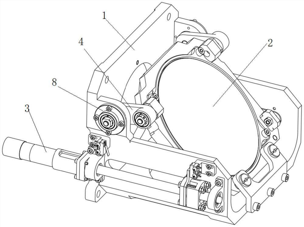
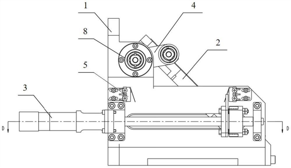
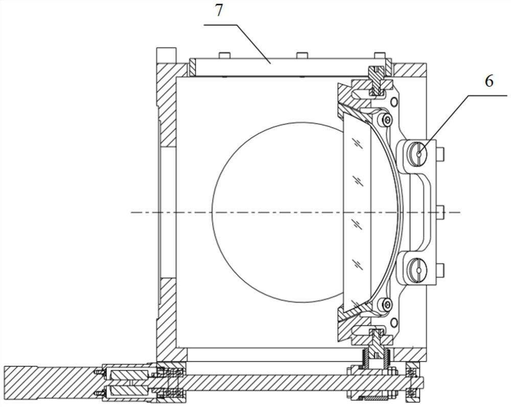
[0028] Such as Figure 1 to Figure 9 As shown, a screw-driven crank cam follow-up mirror switching device includes a support 1, a reflector assembly 2 and a driving mechanism 3 installed on the support 1; The crank 4, the two sides of the lower part are provided with forward and backward linear grooves 7, the middle of the lower front side is provided with a magnet 6 for limiting, and the two ends of the linear groove 7 on one side are provided with micro switches 5, and the upper two sides of the mirror assembly 2 respectively pass through Rotating shaft 13 is connected with the swing end of crank 4 on both sides, cam follower 12 is arranged on both sides of the lower part, and magnetic attraction part 14 corresponding to magnet 6 is arranged in the middle of the lower part front side, and driving mechanism 3 includes ball screw 16 and screw ...


PUM


Abstract

The invention discloses a reflector switching device with a crank cam driven by a lead screw to follow up. Cranks are arranged on the two sides of the upper portion of a support, linear grooves are formed in the two sides of the lower portion of the support, a magnet is arranged in the middle of the lower portion of the support, and microswitches are arranged at the two ends of the linear groove on one side. The two sides of the upper portion of the reflector assembly are connected with crank swing ends on the two sides through rotating shafts respectively, cam followers are arranged on the two sides of the lower portion of the reflector assembly, and a magnetic attraction piece is arranged in the middle of the front side of the lower portion of the reflector assembly. The driving mechanism comprises a ball screw, a screw nut, a motor driving the ball screw, a sliding block and a blocking piece arranged on the screw nut, and a sliding sleeve sleeving the protruding end of the sliding block. The cam follower on one side is in rolling fit with the linear groove on one side, the cam follower on the other side is inserted into the protruding end of the sliding block in a rolling fit mode, the sliding sleeve is in rolling fit with the linear groove on the other side, the blocking piece is used for triggering the microswitches at the two ends of the stroke to trigger the generator, and when the cam followers reach the foremost end of the stroke, the magnet and the magnetic attraction piece are attracted. The device is stable and rapid in switching, free of jamming and high in repeated positioning precision.

Description

technical field [0001] The invention belongs to the field of optical mechanics, and in particular relates to a mirror switching device driven by a lead screw to follow a crank cam. Background technique [0002] Since precise and fast switching of mirrors is required in some optical systems, switching devices with high repeat positioning accuracy, high switching speed, and smooth switching are required. At present, the mirror switching devices adopted at home and abroad generally adopt translation switching mechanism and rotation switching mechanism. Although the translation switching mechanism can realize the rapid switching of the mirror group, in order to ensure the repeated positioning accuracy of the mirror group, its limit and self-locking mechanisms are generally more complicated, the processing and adjustment are also more complicated, and it will occupy a large space volume. This switching mechanism is not suitable for optomechanical systems with limited space. The...

Claims


Application Information

Patent Timeline
Patent Type & Authority Applications(China)
IPC IPC(8): G02B7/182G02B7/198
CPCG02B7/1821G02B7/198
Inventor 黄龙凯吴耀熊涛左腾宋鹏飞艾飞
Owner HUBEI JIUZHIYANG INFRARED SYST CO LTD
Learn More