Slow start circuit suitable for boosting power supply of power supply

A technology of boosting power supply and power supply, applied in the field of electric meters, can solve problems such as excessive transistor current, frequent MCU reset, affecting battery power supply, etc., to achieve the effects of improving stability, low production cost, and simple circuit structure design

Pending Publication Date: 2022-01-25
NINGBO SANXING INTELLIGENT ELECTRIC
View PDF0 Cites 0 Cited by
  • Summary
  • Abstract
  • Description
  • Claims
  • Application Information

AI Technical Summary

Problems solved by technology

[0003] Most of the existing schemes use two triode conversion circuits to supply power to the booster circuit. Because the electrolytic capacitor needs to be charged in the initial stage of power supply boosting, this will cause the current of the triode to be too large at the beginning of opening, and the voltage of the battery and other power sources will be pulled too low, which will affect the battery. Waiting for the power to supply power to the MCU makes the MCU reset frequently, resulting in circuit instability

Method used


Image

  • Slow start circuit suitable for boosting power supply of power supply
  • Slow start circuit suitable for boosting power supply of power supply

Examples


Embodiment Construction

[0022] Embodiments of the present invention are described in detail below, examples of which are shown in the drawings, wherein the same or similar reference numerals designate the same or similar elements or elements having the same or similar functions throughout. The embodiments described below by referring to the figures are exemplary only for explaining the present invention and should not be construed as limiting the present invention.

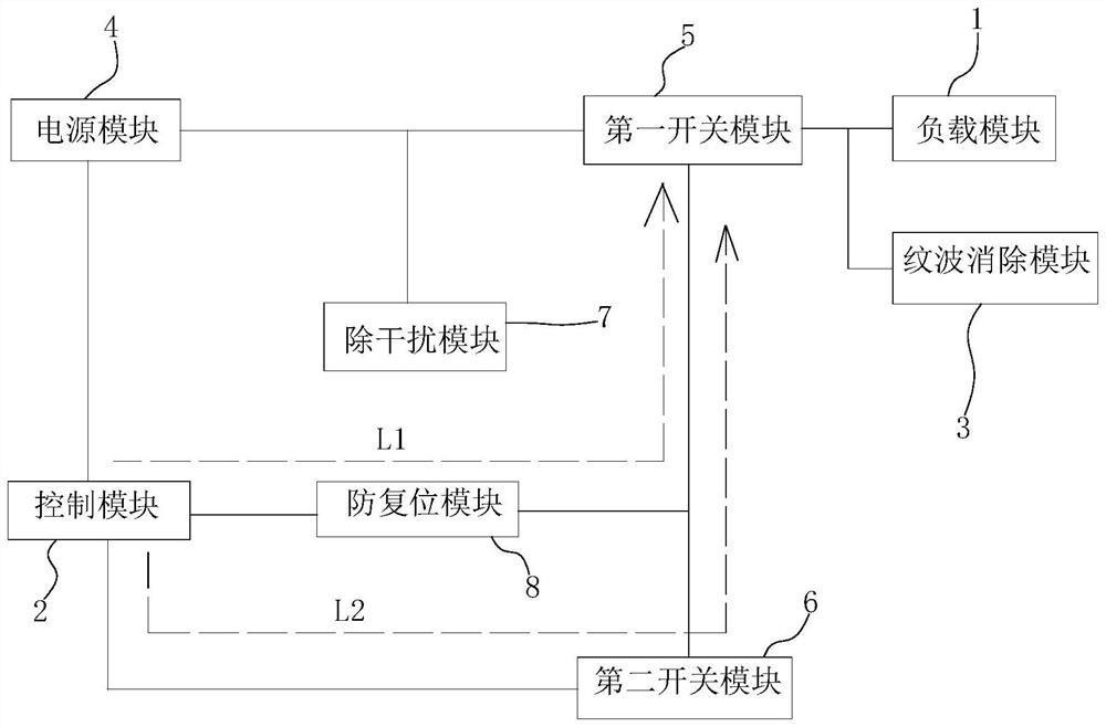
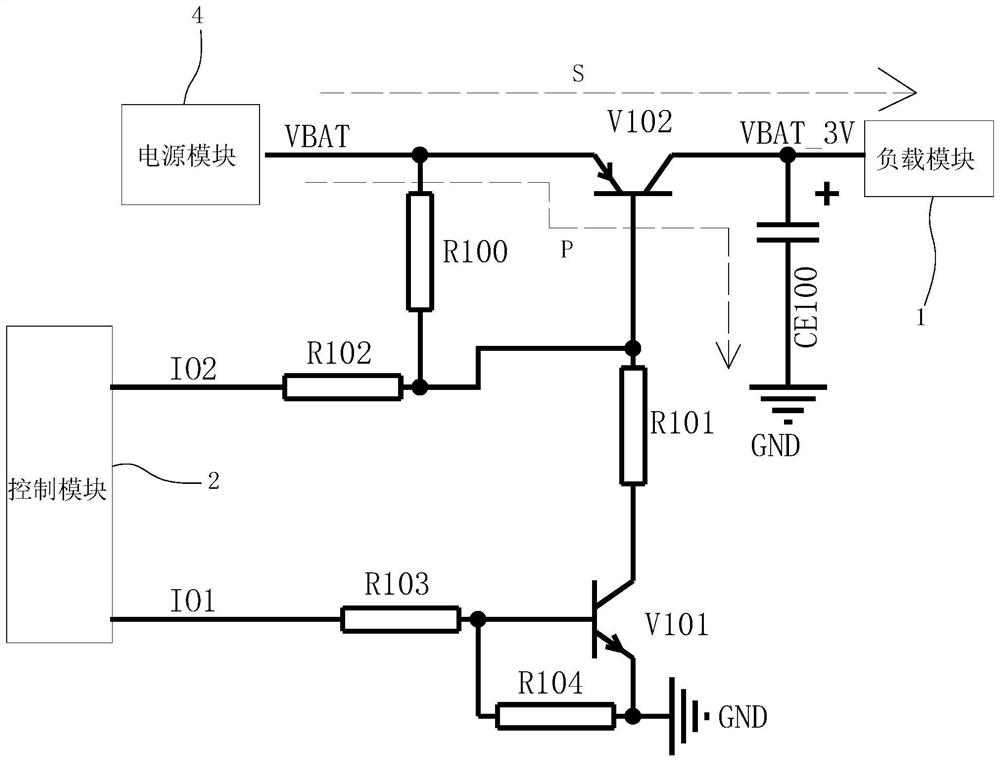
[0023] Figure 1-2 It shows a preferred embodiment of the slow-start circuit suitable for power boosting power supply in this application. As shown in the figure, the circuit includes a load module 1, a control module 2, a ripple elimination module 3, a power module 4, and a first switch module 5 and the second switch module 6, the power supply module 4 is connected with the control module 2.

[0024] As mentioned above, the existing conversion circuit composed of two triodes has an excessive charging current at the initial stage of boo...


PUM


Abstract

The invention relates to a slow start circuit suitable for boosting power supply of a power supply. The slow start circuit comprises a load module, a control module, a ripple elimination module, a power supply module, a first switch module and a second switch module; the power supply module is connected with the control module; the first switch module is arranged at the output end of the power supply module and connected with the load module and the ripple elimination module, so that a boosting power supply branch circuit and an absorption branch circuit can be formed; and the first switch module is connected with the control module, so that a first switch branch circuit can be formed; the first switch branch circuit acts at the initial stage of boosting power supply so as to enable the boosting power supply branch circuit and the absorption branch circuit to be synchronously switched on; the second switch module is connected with the control module and the first switch module, so that a second switch branch circuit can be formed; the second switch branch circuit acts after the first switch branch circuit acts for T time so as to cooperate with the first switch branch circuit to jointly control boosting power supply of the power supply module, wherein T is not less than the charging time of the absorption branch circuit. The stability of the slow start circuit is improved.

Description

technical field [0001] The invention relates to the technical field of ammeters, in particular to a slow-start circuit suitable for boosting power supply. Background technique [0002] With the expansion of smart terminals, such as the application market of prepaid electric meters, the demand for CIUs is increasing, and it is becoming more and more common to boost power supplies such as batteries. In order to reduce the back-end ripple, designers usually add An electrolytic capacitor is added at the back end, and how to control the battery to supply power to the boost circuit at a specific time through the chip has become a matter that every designer must consider. [0003] Most of the existing schemes use two triode conversion circuits to supply power to the booster circuit. Because the electrolytic capacitor needs to be charged in the initial stage of power supply boosting, this causes the current of the triode to be too large at the beginning of opening, and the voltage o...

Claims


Application Information

Patent Timeline
IPC IPC(8): H02M1/34H02M1/36H02M1/14H02M3/156
CPCH02M1/34H02M1/36H02M1/14H02M3/156
Inventor 刘丹何瑛俏
Owner NINGBO SANXING INTELLIGENT ELECTRIC
Why Eureka
Try Eureka