Steelmaking ladle

A technology of body and support frame, which is used in casting molten material containers, metal processing equipment, casting equipment, etc., can solve the problems of splashing, safety accidents, and high risks of molten steel, so as to improve accuracy, improve safety, and reduce waste. Effect

Active Publication Date: 2022-01-28
ZHEJIANG JINHUIHUA SPECIAL REFRACTORIES
View PDF16 Cites 0 Cited by
  • Summary
  • Abstract
  • Description
  • Claims
  • Application Information

AI Technical Summary

Problems solved by technology

[0003] At present, when the small steelmaking ladles on the market are in use, one worker usually directs another worker to turn the runner on the steelmaking ladle from a distance, so that the transmission structure drives the steelmaking ladle to rotate around the bearing shaft to a predetermined angle , and then the molten steel flows from the steel ladle into the feed port of the mold to be poured. Because the height of the molten steel in the steel ladle is high, the molten steel will splash and the risk is high. In the material mouth, some waste will be caused, and the gear that drives the bearing shaft to rotate is usually fixedly connected by the cooperation between the keyway and the key. After the key is sheared and damaged under long-term use, the molten steel in the ladle will be broken All poured out, resulting in safety accidents, so there is an urgent need for a method that can reduce the number of labor, the molten steel can accurately enter the feed port, reduce the waste of molten steel, and the molten steel will not cause large splashes. A steelmaking ladle in which molten steel does not pour out

Method used


Image

  • Steelmaking ladle
  • Steelmaking ladle
  • Steelmaking ladle

Examples


Embodiment Construction

[0021] In order to make the technical means, creative features, goals and effects achieved by the present invention easy to understand, the present invention will be further described below in conjunction with specific embodiments.

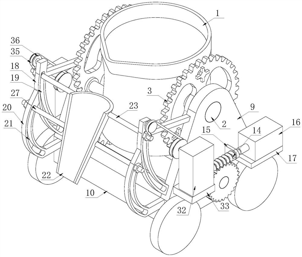
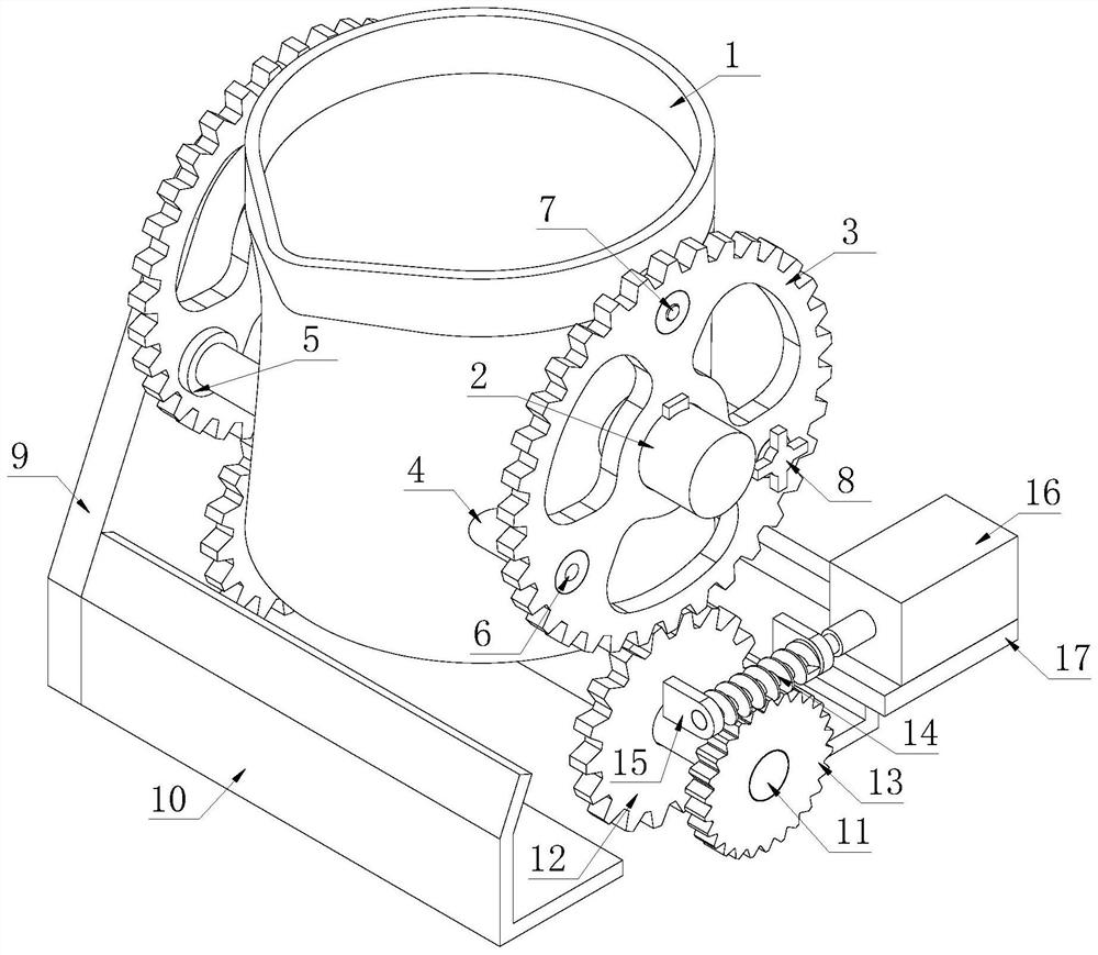
[0022] Such as Figure 1-Figure 4 As shown, a steelmaking ladle according to the present invention includes a steelmaking ladle body 1, and both sides of the outer wall of the steelmaking ladle body 1 are fixedly connected with a bearing shaft 2, and the outside of the bearing shaft 2 can be moved through a keyway and a key. The first gear 3 is disassembled and connected. The inside of the first gear 3 runs through and is slidably connected with three positioning shafts 4 distributed in an annular array. The positioning shafts 4 are fixedly connected to the outer wall of the steelmaking ladle body 1. The positioning shafts 4 The outer peripheral surface is fixedly connected with a retaining ring 5, the retaining ring 5 fits with the first gear 3, ...


PUM


Abstract

The invention relates to the technical field of steelmaking ladles, in particular to a steelmaking ladle which comprises a steelmaking ladle body, bearing shafts are fixedly connected to the two sides of the outer wall of the steelmaking ladle body, first gears are detachably connected to the outer portions of the bearing shafts through key grooves and keys, three positioning shafts distributed in an annular array mode penetrate through and are slidably connected into the first gear, and the positioning shafts are fixedly connected with the outer wall of the steelmaking ladle body. When the steelmaking ladle body rotates, a flow guide pipe can move relatively, so that the top end of the flow guide pipe is always located under a discharging port of the steelmaking ladle body, molten steel flows onto the flow guide pipe firstly and then enters the feeding port of the mold when flowing out of the steelmaking ladle body, and the flow guide effect is achieved; the quantity of molten steel falling from the high position and splashing out is reduced, the accuracy of the molten steel entering the feeding port is improved, the safety is improved, and waste of the molten steel is reduced.

Description

technical field [0001] The invention relates to the technical field of steelmaking ladles, in particular to a steelmaking ladle. Background technique [0002] Steelmaking ladle, also known as ladle or ladle, is used in steelmaking plants and foundries to receive molten steel and perform pouring operations before open hearth furnaces, electric furnaces or converters. The steel ladle is a container of refractory material. The smelted molten steel is poured into the ladle from the open hearth furnace, electric furnace or converter. The molten steel can be refined in the ladle, and then the molten steel is transferred to the tundish by the ladle. The ladle is usually divided into two types, one One is to lift by a hook, and use the electric hoist to drive the hook to pull one side of the bottom of the ladle up to complete the pouring of molten steel. The other is to turn the runner on the ladle by the staff, and use the transmission structure to drive the ladle to rotate, thereb...

Claims


Application Information

Patent Timeline
IPC IPC(8): B22D41/00B22D41/12B22D41/04
CPCB22D41/00B22D41/12B22D41/04Y02P10/20
Inventor 孟淡军赵欣豪
Owner ZHEJIANG JINHUIHUA SPECIAL REFRACTORIES
Why Eureka
Try Eureka