
Fixed-position follow-up rigid supporting mechanism

A rigid support, fixed position technology, applied in the direction of large fixed members, lifting devices, metal processing machinery parts, etc., can solve problems such as poor support stiffness, platform instability, local structural displacement, etc.

Active Publication Date: 2022-01-28
WUHAN MARINE MACHINERY PLANT
View PDF7 Cites 0 Cited by
  • Summary
  • Abstract
  • Description
  • Claims
  • Application Information

AI Technical Summary

Problems solved by technology

In this way, once the oil circuit or valve parts leak, it is very easy to cause platform instability and safety accidents; at the same time, because the hydraulic oil in the oil cylinder still has a certain degree of compressibility, its support rigidity is poor. For large platforms, Due to the micro-movement of the support cylinder after being stressed, it may cause a large displacement of the local structure and poor stability

Method used


Image

  • Fixed-position follow-up rigid supporting mechanism
  • Fixed-position follow-up rigid supporting mechanism
  • Fixed-position follow-up rigid supporting mechanism

Examples


Embodiment 1

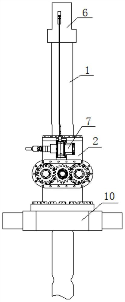
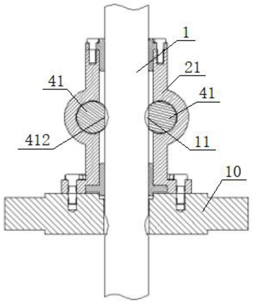
[0043] see Figure 1-Figure 7, a fixed position follow-up rigid support mechanism, including a follow-up rigid support rod 1, a lock 2, a connecting sleeve 6, a cable displacement sensor 7, and a mounting seat 10, the upper end of the follow-up rigid support rod 1 and the connecting sleeve 6 The bottom of the connecting sleeve 6 is fixedly connected, the upper end of the connecting sleeve 6 is provided with a through hole fixedly connected with the hinge shaft at the bottom of the support platform 8, and the lower end of the follow-up rigid support rod 1 passes through the locker 2 and the mounting seat 10 in turn and then extends downward. , the bottom of the housing 21 of the locker 2 is fixedly connected to the drive cylinder support base 9 through the mounting seat 10 of the hinge structure, and the inside of the housing 21 is provided with the drive shaft assembly 3, which is arranged side by side Two sets of locking shaft assemblies 4 on both sides, the drive shaft assem...

Embodiment 2

[0045] The difference from the example is:

[0046] The upper and lower openings of the housing 21 are respectively provided with a No. 1 guide sleeve 22 and a No. 2 guide sleeve 23. match.


PUM


Abstract

A fixed-position follow-up rigid supporting mechanism comprises a follow-up rigid supporting rod and a locking device, the upper end of the follow-up rigid supporting rod is connected with the bottom of a supporting platform, the lower end of the follow-up rigid supporting rod penetrates through the locking device and then extends outwards, the bottom of a shell of the locking device is connected with a driving oil cylinder supporting base, and a driving shaft assembly and locking shaft assemblies on the two sides of the driving shaft assembly are arranged in the shell. The driving shaft assembly comprises a driving shaft and a driving gear arranged on the driving shaft in a sleeving mode, one end of the driving shaft is in running fit with the shell through a first bearing, the other end of the driving shaft extends to the outer portion of the locking device, and the locking shaft assembly comprises a locking shaft and a locking gear arranged at one end of the locking shaft in a sleeving mode and meshed with the driving gear. The end of the locking shaft is rotationally matched with the shell through a second bearing assembly, the middle section of the locking shaft is a cylinder with a cutting plane, the arc-shaped face of the middle section can be matched with an arc-shaped groove in the outer wall of the follow-up rigid supporting rod, and the depth of the arc-shaped groove is smaller than or equal to the cutting thickness of the cutting plane. The mechanism realizes reliable fixing and supporting after the platform is in place.

Description

technical field [0001] The invention belongs to the field of mechanical locking, and in particular relates to a fixed-position follow-up rigid support mechanism, which is used to solve the problem of reliable fixed support after a tilting or lifting platform with high safety requirements is in place. Background technique [0002] For the traditional tilting or lifting platform, the tilting around the hinge point or the lifting along the fixed axis is realized through the oil cylinder, etc. After it is in place, the oil circuit is locked by the hydraulic lock in the hydraulic system, so that the oil cylinder supports the platform. In this way, once the oil circuit or valve parts leak, it is very easy to cause platform instability and safety accidents; at the same time, because the hydraulic oil in the oil cylinder still has a certain degree of compressibility, its support rigidity is poor. For large platforms, Due to the micro-movement of the support cylinder after being stre...

Claims


Application Information

Patent Timeline
IPC IPC(8): B23Q1/25B66F13/00
CPCB23Q1/25B66F13/00
Inventor 王宝宝李祖荟孟华
Owner WUHAN MARINE MACHINERY PLANT
Learn More