Assembly type floor sound insulation material production line

A sound insulation material and production line technology, applied in the field of sound insulation materials, can solve problems affecting cleaning efficiency, floor sound insulation board trouble, and floor sound insulation board cutting efficiency, etc., to achieve strong linkage and improve cutting efficiency.

Active Publication Date: 2022-01-28
重庆易高实业有限公司
View PDF7 Cites 0 Cited by
  • Summary
  • Abstract
  • Description
  • Claims
  • Application Information

AI Technical Summary

Problems solved by technology

[0002] In order to create a better living environment and a better working environment, more and more people are laying upper and lower sound insulation panels in their studios or living rooms to ensure a good sound insulation effect. There is an assembled floor sound insulation board on the market, and this kind of floor sound insulation board needs to be cut during the actual production process on the production line to meet the production requirements. In the production line under the existing technology The cutting device of the ground sound insulation board cannot realize the rapid positioning and fixing of the ground sound insulation board in the actual use process, which makes it very troublesome to fix and remove the floor sound insulation board every time, which seriously affects the cutting efficiency of the ground sound insulation board and thus It affects the production efficiency of the entire production line. In addition, more debris will be generated during the cutting process. The existing cutting device is not equipped with a debris collection device, which makes it troublesome to disperse the debris on the cutting device and affect cleaning. work efficiency

Method used


Image

  • Assembly type floor sound insulation material production line
  • Assembly type floor sound insulation material production line
  • Assembly type floor sound insulation material production line

Examples


Embodiment Construction

[0024] The following will clearly and completely describe the technical solutions in the embodiments of the present invention with reference to the accompanying drawings in the embodiments of the present invention. Obviously, the described embodiments are only some, not all, embodiments of the present invention. Based on the embodiments of the present invention, all other embodiments obtained by persons of ordinary skill in the art without making creative efforts belong to the protection scope of the present invention.

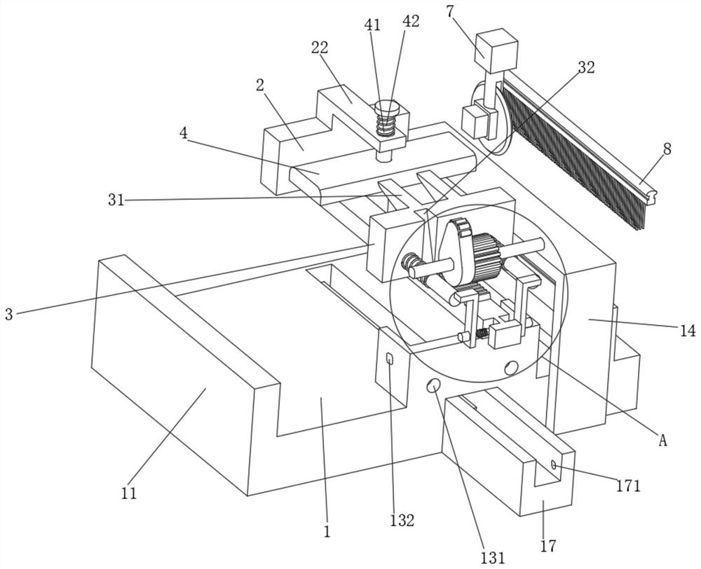
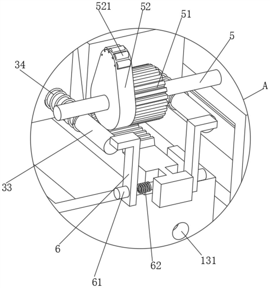
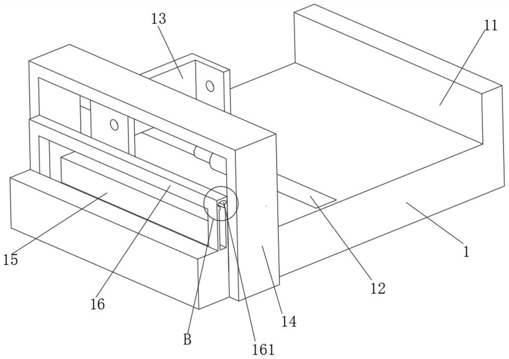
[0025] see Figure 1 to Figure 6 , the present invention provides a technical solution:

[0026] Assembled sound insulation material production line, including a cutting device 1, one end of the cutting device is welded and fixed to a limiting plate 11, and the end of the cutting device 1 away from the limiting plate 11 is provided with a moving groove 12, and a dovetail rail is welded and fixed in the moving groove 12 121, and the upper end of the port of th...


PUM


Abstract

The invention relates to the technical field of sound insulation materials, in particular to an assembly type sound insulation material production line which comprises a cutting device, a limiting plate is fixedly welded to one end of the cutting device, a moving groove is formed in the end, away from the limiting plate, of the cutting device, and a dovetail rail is fixedly welded to the interior of the moving groove. A fixing plate is welded and fixed to the upper end of the end opening of the moving groove, and guide holes are symmetrically formed in the fixing plate; through arranged locking plate, first clamping plate can be pulled to move towards one side close to floor sound insulation plate, then gear is driven to rotate under action of rack on first clamping plate, second clamping plate also moves towards one side close to floor sound insulation plate under action of cam, and then two clamping plates move oppositely to clamp floor sound insulation plate. And meanwhile, a pressing plate moves downwards to press the floor acoustic panel under the action of an inclined plane ejector block, so that the floor acoustic panel can be quickly positioned and fixed, the stability of the floor acoustic panel in the cutting process is guaranteed, and the cutting efficiency is greatly improved.

Description

technical field [0001] The invention relates to the technical field of sound-insulating materials, in particular to an assembled sound-insulating material production line. Background technique [0002] In order to create a better living environment and a better working environment, more and more people are laying upper and lower sound insulation panels in their studios or living rooms to ensure a good sound insulation effect. There is an assembled floor sound insulation board on the market, and the floor sound insulation board needs to be cut during the actual production process on the production line to meet the production requirements. In the production line under the existing technology The cutting device of the ground sound insulation board cannot realize the rapid positioning and fixing of the ground sound insulation board in the actual use process, which makes it very troublesome to fix and remove the floor sound insulation board every time, which seriously affects the...

Claims


Application Information

Patent Timeline
Patent Type & Authority Applications(China)
IPC IPC(8): B26D7/02B26D7/18
CPCB26D7/025B26D7/18
Inventor 丁卫国
Owner 重庆易高实业有限公司
Why Eureka
Try Eureka