
A preparation method of a shape support device for processing military figurines
A support device and shape technology, which is applied in the field of preparation of shape support devices for processing military figurines, can solve the problems of the influence of steel wire mesh shape, troublesome construction process, and difficulty in manufacturing military figurines, so as to reduce the difficulty of shaping and ensure installation The effect of stability and precise docking
- Summary
- Abstract
- Description
- Claims
- Application Information
AI Technical Summary
Problems solved by technology
Method used
Image

Examples
Embodiment Construction
[0037] In order to facilitate the understanding of those skilled in the art, the structure of the present invention will be further described in detail with the embodiments in conjunction with the accompanying drawings:
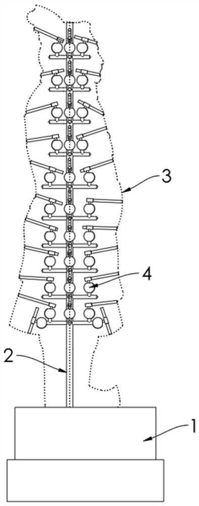
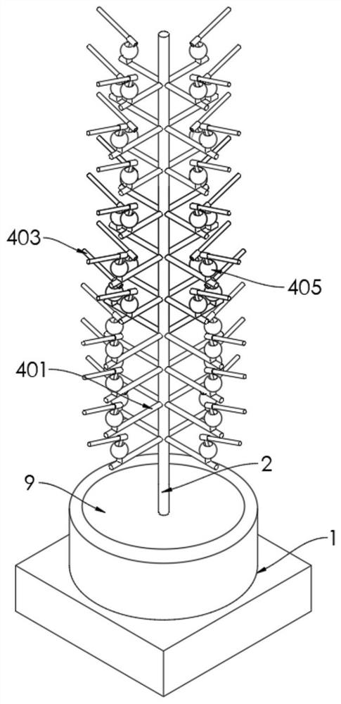
[0038] refer to Figure 1-6 , a shape support device for processing military figurines, comprising
[0039]Base 1, the middle of the base 1 is affixed with a support rod 2 upwards, and four corresponding molding rods 3 are affixed upward at an equal angle of 90° on the base 1, and the bottom of the molding rod 3 fixed on the base 1, and the tops of the molding rods 3 are respectively fixed on the top ends of the supporting rods 2;
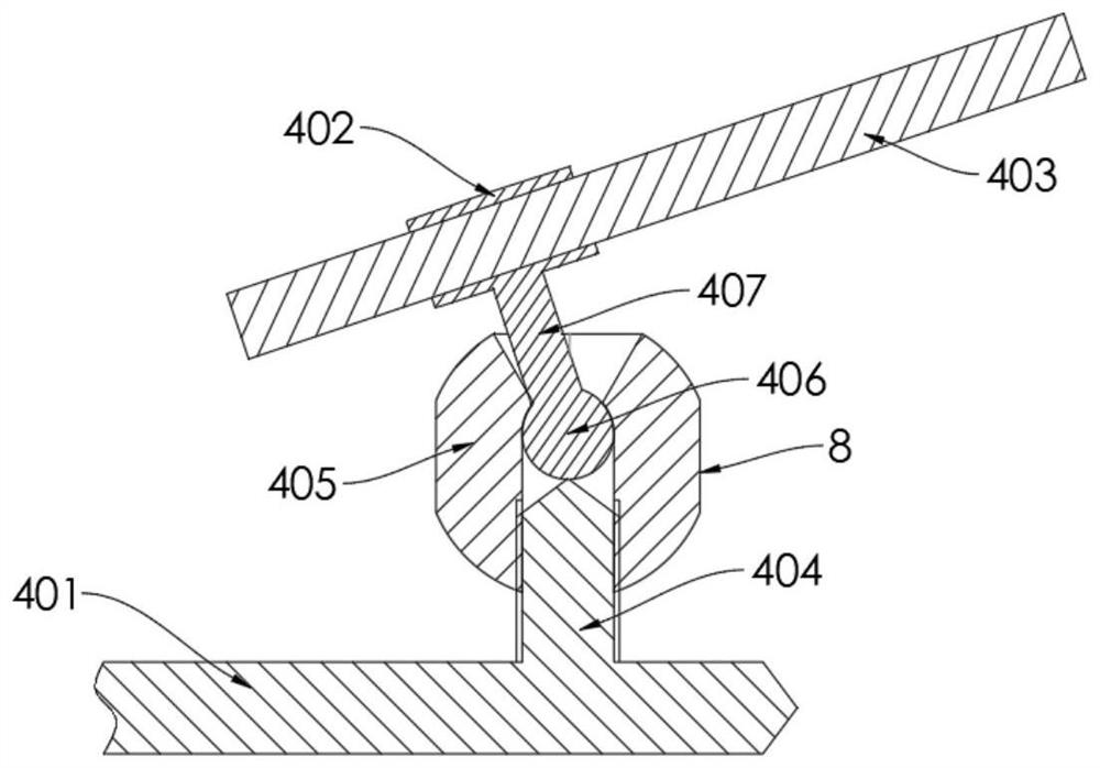
[0040] The support mechanism 4 includes four rows of horizontal support rods 401 fixed side by side on the support rods 2 at equal angles. The outer ends of the lateral support rods 401 are respectively located inside the corresponding molding rods 3. Corresponding installation pipes 402 are installed on the rods 401 with adjust...
PUM
 Abstract
Description
Claims
Application Information