
Cargo conveying system and cargo conveying method

A technology of conveying system and conveying direction, applied in the direction of conveyor objects, conveyors, mechanical conveyors, etc., can solve the problem of low efficiency of cargo transportation, and achieve the effect of improving efficiency

Pending Publication Date: 2022-01-28
HAI ROBOTICS CO LTD
View PDF0 Cites 0 Cited by
  • Summary
  • Abstract
  • Description
  • Claims
  • Application Information

AI Technical Summary

Problems solved by technology

[0005] Embodiments of the present disclosure provide a cargo conveying system and a cargo conveying method, which are used to solve the problem of relatively low cargo conveying efficiency in the cargo conveying system

Method used


Image

  • Cargo conveying system and cargo conveying method
  • Cargo conveying system and cargo conveying method
  • Cargo conveying system and cargo conveying method

Examples


Embodiment 1

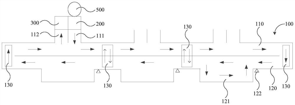
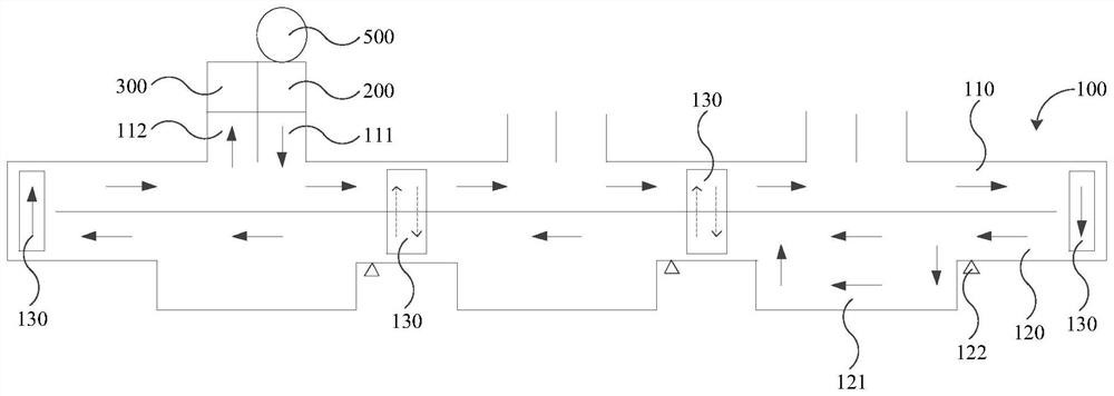
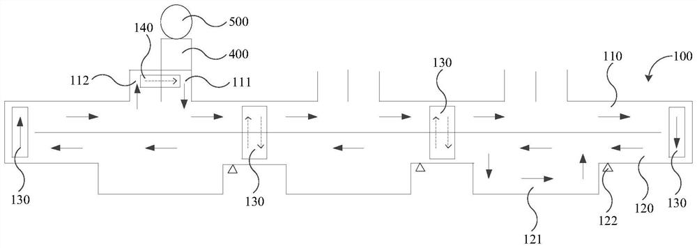
[0074] figure 1 A schematic top view of a cargo conveying system provided by an embodiment of the present disclosure Figure 1 ; figure 2 A schematic top view of a cargo conveying system provided by an embodiment of the present disclosure Figure II ; image 3 A schematic top view of a cargo conveying system provided by an embodiment of the present disclosure Figure three ; Figure 4 Schematic top view of a part of the closed-loop conveyor line and sorting conveyor line provided for the embodiments of the present disclosure Figure 1 ; Figure 5 Schematic top view of a part of the closed-loop conveyor line and sorting conveyor line provided for the embodiments of the present disclosure Figure II ; Figure 6 for in Figure 4 A schematic side view of an auxiliary conveyor line set above the picking conveyor line in ; Figure 7 It is a structural schematic diagram of docking between a handling robot and an unloader provided by an embodiment of the present disclosure. ...

Embodiment 2

[0110] Figure 8 A process flow of a cargo delivery method provided by an embodiment of the present disclosure Figure 1 ; Figure 9 A process flow of a cargo delivery method provided by an embodiment of the present disclosure Figure II ; Figure 10 A process flow of a cargo delivery method provided by an embodiment of the present disclosure Figure three ; Figure 11 A process flow of a cargo delivery method provided by an embodiment of the present disclosure Figure four .

[0111] refer to Figure 8 to Figure 11The embodiment of the present disclosure provides a cargo delivery method, which is applied to the cargo delivery system in Embodiment 1. The components and specific structure of the cargo delivery system involved in this embodiment can refer to the description in Embodiment 1. The execution subject of the goods delivery method may be a management device, which may include a computer, a server, and a chip, etc., and the management device may control the worki...


PUM


Abstract

The invention provides a cargo conveying system and a cargo conveying method, and relates to the technical field of intelligent warehousing.The cargo conveying system comprises a closed-loop conveying line; the closed-loop conveying line comprises a first conveying section and a second conveying section which are sequentially connected end to end; at least two groups of cargo inlets and outlets are formed in one side of the first conveying section at intervals; at least two sorting conveying lines are arranged on one side of the second conveying section; at least three first transferring devices are arranged on the closed-loop conveying line, wherein two of the first transferring devices are located at the two ends of the first conveying section correspondingly, and the other first transferring devices are located between any two sorting conveying lines and between any two groups of cargo inlets and outlets; and the first transferring devices transfer the cargoes on the second conveying section to the first conveying section or transfer the cargoes on the first conveying section to the second conveying section. The cargo conveying system and the cargo conveying method are beneficial to improving the cargo conveying efficiency.

Description

technical field [0001] The present disclosure relates to the technical field of intelligent warehousing, and in particular to a cargo conveying system and a cargo conveying method. Background technique [0002] With the rapid development of artificial intelligence technology, automation technology and information technology, the intelligence level of terminal logistics is also increasing, and intelligent warehousing is an important link in the logistics process. [0003] In intelligent warehousing, the cargo conveying system is the main equipment that can realize automatic conveying and sorting operations. The cargo conveying system can reduce human heavy physical labor and improve the efficiency of conveying and sorting operations. In the related art, the cargo conveying system includes multiple U-shaped picking workstations, and each U-shaped picking workstation has cargo import and cargo export. When working, the goods that need to enter multiple U-shaped picking worksta...

Claims


Application Information

Patent Timeline
IPC IPC(8): B65G1/04B65G37/00B65G47/74
CPCB65G1/04B65G37/00B65G47/74
Inventor 陈叶广汪奎
Owner HAI ROBOTICS CO LTD
Learn More